[Article 2 of 2.] This is a summary of the alternate definitions and uses of driving logic relationships between activities in project schedules, as applied in Primavera P6 and Microsoft Project software. Driving relationships are often considered fundamental elements of the project critical path.
This winter I worked with a colleague to prepare a paper – Interpreting Logic Paths in Multi-Calendar Project Schedules – for presentation at this year’s AACE International Conference and Expo in Chicago (Covid-19) virtual world. It’s a deep dive into the Multiple Float Path calculation options in Primavera P6 scheduling software. During the technical study, I had a lot of opportunities to think about driving logic relationships. I’ve summarized the standard definitions and uses in an earlier article. This entry summarizes the alternate versions of driving logic relationships that sometimes arise.
The Importance of Driving Logic
The planning and execution of complex projects requires the project team to understand, implement, and communicate the consequences of schedule logic flow to the other stakeholders. Through schedule logic, each activity in the project has the potential to constrain or disrupt numerous other activities – and to be constrained or disrupted by them. The most obvious artifacts of logic flow are the important logic paths, like the critical path, the Longest Path (in Primavera P6), or the driving path to a key delivery milestone. Regardless of the detailed definition, each of these important paths is governed by driving logic relationships from the first activity to the last activity in the path.
Late-Dates and Bi-Directional Driving Relationships in Primavera P6
From the earlier article, a relationship is considered driving (under the standard definitions) when its successor’s early dates are constrained by the relationship, during the forward pass of the CPM calculations. That is, standard driving relationships are early-dates driving relationships. A late-dates driving relationship, in contrast, is one that constrains the late dates of the predecessor, during the backward pass. When an activity has multiple successors, then one or more of these successor relationships may be controlling the late dates, and hence the total float, of the selected activity; this is a late-dates driving relationship.
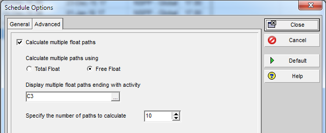
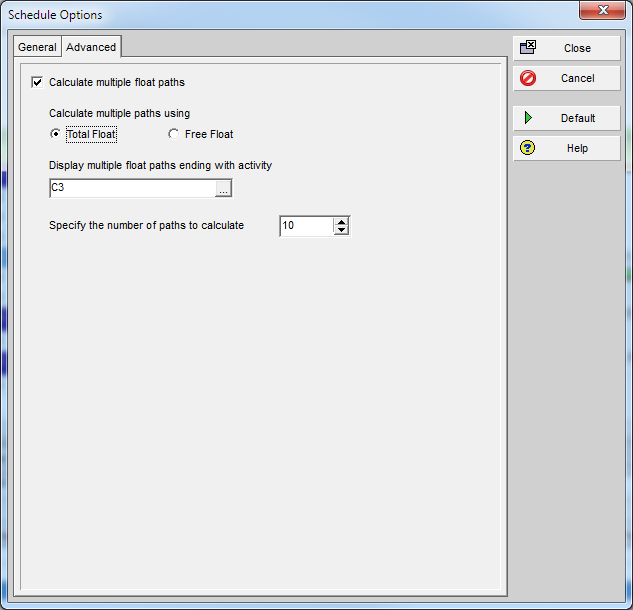
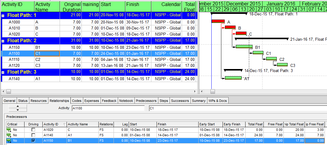
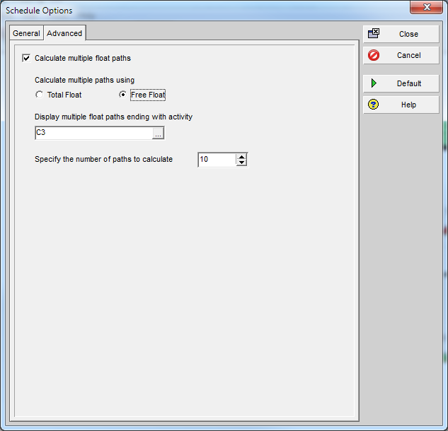
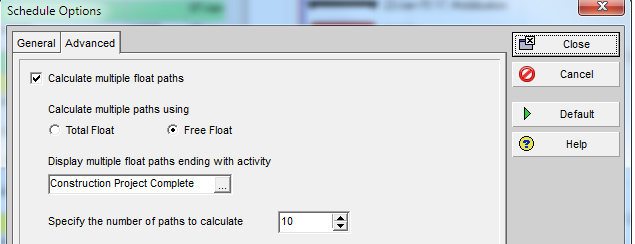
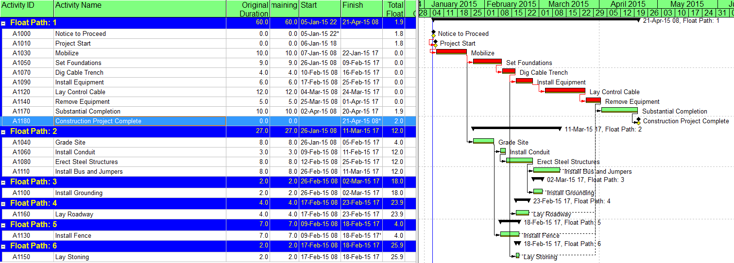
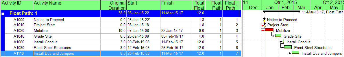
Identification of late-dates driving relationships is a key factor in P6’s Multiple Float Path (MFP) calculation. Under the total float calculation option, a relationship can be assigned to a driving “float path” only if it meets the criteria for both early-dates and late-dates driving relationships. That is, it possesses bi-directional driving logic. Since P6 does not flag or otherwise mark such relationships, the results of multiple float path calculations with the total float option can be confusing. Full understanding of the float paths may require a detailed examination of relationship and activity floats, especially when multiple calendars or constraints are involved.
For more information on MFP calculations in P6, check out these other entries in the blog:
Beyond the Critical Path – the Need for Logic Analysis of Project Schedules
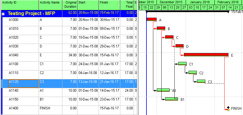
P6 Multiple Float Path Analysis – Why Use Free Float Option
Relationship Free Float and Float Paths in Multi-Calendar Projects (P6 MFP Free Float Option)
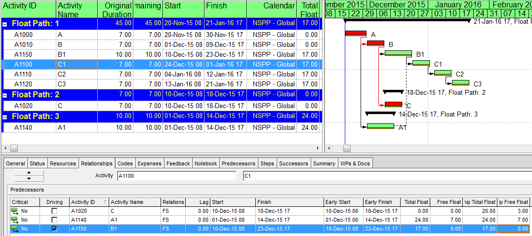
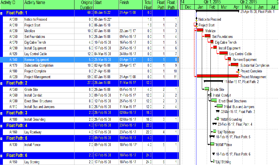
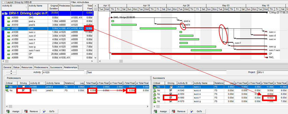
Aside from the MFP calculation option in P6, this type of driving logic is useful mainly for prioritizing driving successors when click-tracing through the schedule network in the forward direction – perhaps for schedule validation or disruption analysis. For example, consider the selected activity (A1020, “Task”) in the P6 version of our simple project below. A glance at the late-date bars shows that only one of its five driven successors (A1060, “succ f”) is responsible for the late dates (and total float) of the selected task. The corresponding relationship possesses bi-directional driving logic and marks the forward continuation of the total-float-based driving path. In the relationship tables, the “Driving” checkboxes already indicate the relationships with early-dates driving logic. When exploring forward, most P6 users will simply click to the driven successor activity that is “Critical” or has the lowest total float value, and that will be correct much of the time. When multiple constraints and/or calendars exist, however – or when the path being explored is far from critical – then late-dates driving logic is indicated when the “Relationship Total Float” equals the total float of the predecessor activity, as highlighted in the figure.
Late-Dates and Bi-Directional Driving Relationships in BPC Logic Filter
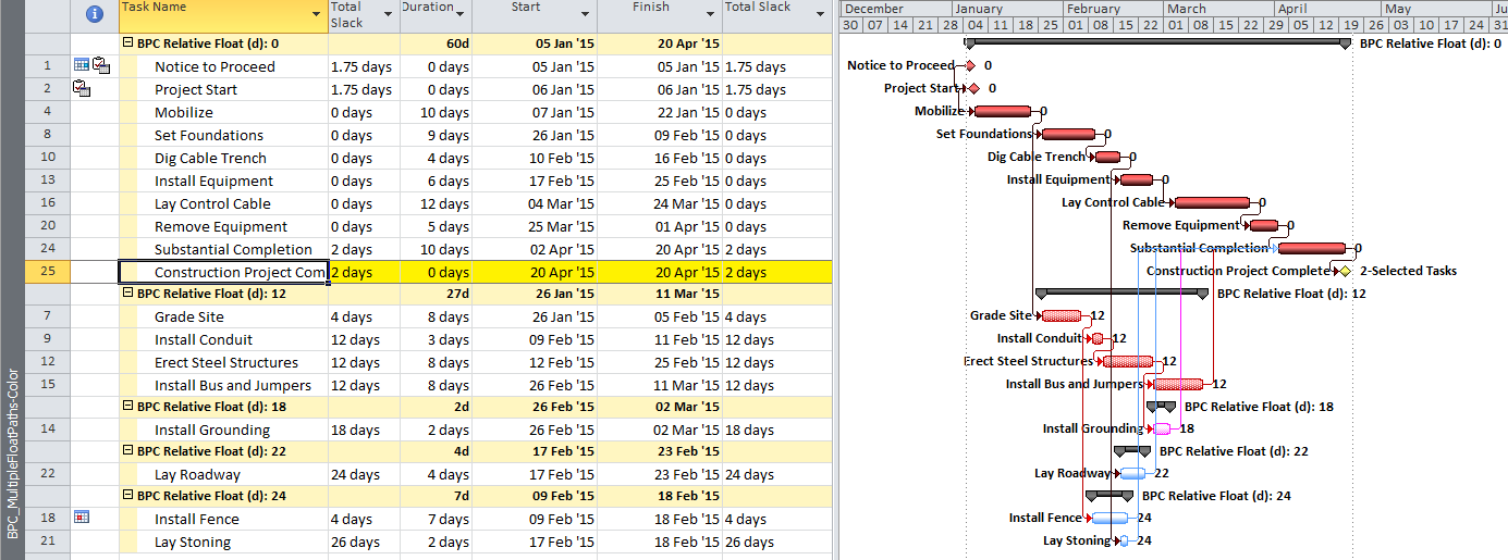
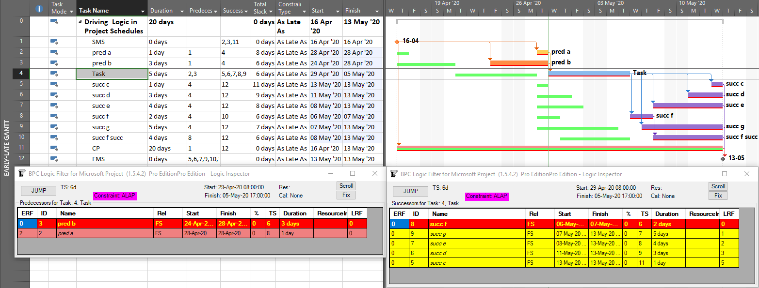
With no built-in alternatives, BPC Logic Filter automatically identify all three types of driving relationships – early-dates, late-dates, and bi-directional – in Microsoft Project schedules. The next figure repeats the same simple example project from the earlier article, with additional bars for early and late dates (green and red) and the task paths shown earlier (orange, gold, purple.) Within the logic inspector tables, bi-directional driving relationships are highlighted (red/yellow) and shown on top. Among those relationships that are NOT bi-directional drivers, early-date drivers are shown in the same yellow as before, and late-date drivers are shown in pale red. As usual, the logic inspector’s jump buttons make for easy, logic-based navigation through the schedule.

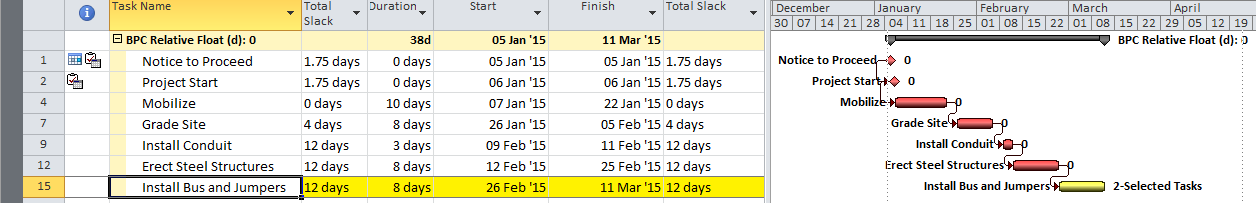
Unlike MSP’s built-in task path bar styles, the logic inspector tables are equally effective at illustrating driving logic in backward-scheduled projects. This is demonstrated below, where the same example project has been re-configured to Schedule from: Project Finish Date. Interestingly, while the scheduled dates clearly change, the nature of driving logic relationships does not.
For further information on driving logic in backward-scheduled projects, check out this earlier entry: Driving Logic in Backward Scheduled Projects (Microsoft Project), which pre-dated the introduction of late-dates driving calculations in the logic inspector.
Resource Driving Logic Relationships in BPC Logic Filter
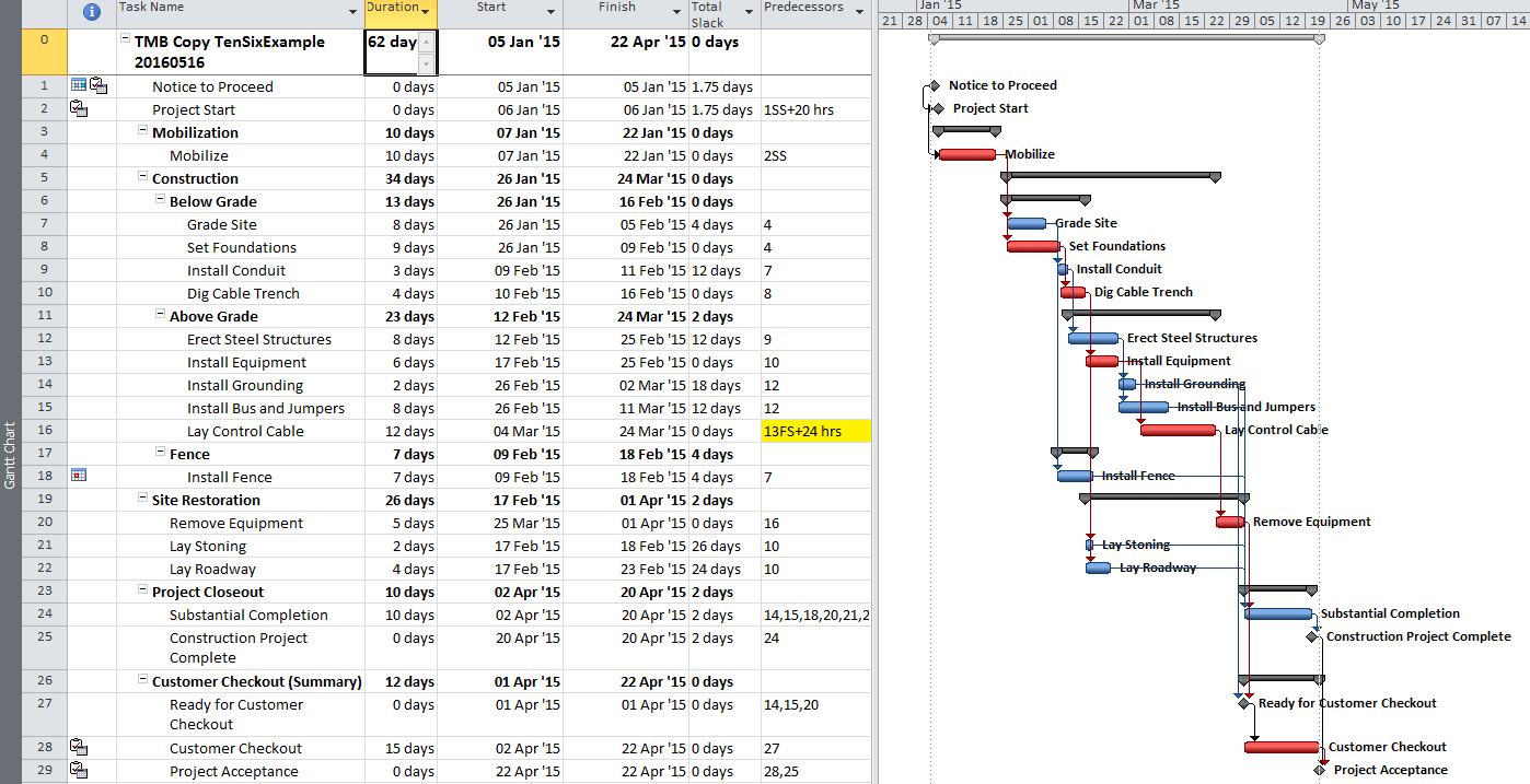
When resource leveling is imposed in a P6 or MSP project schedule, some tasks are delayed from their CPM-based early dates until resources become available – after completion of other tasks. In the figure below, a single resource has been assigned to the five successors of the “Task,” and the resulting overallocation of the resource has been resolved by leveling the schedule using the simplest options. As a result, the project finish milestone has been delayed by three days, and the critical path has shifted.
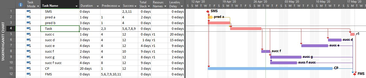
The leveling process creates implied driving relationships between tasks that demand the same resources. BPC Logic Filter infers these “ResDrvr” relationships. As shown below, the resulting resource-constrained driving logic paths are typically very different from those identified using CPM logic alone.

The consequences of resource driving logic are further addressed in these earlier articles:
The Resource Critical Path – Logic Analysis of Resource-Leveled Schedules (MS Project), Part 2
Hierarchical (Parent-Child) Driving Logic Relationships in Microsoft Project
Unlike other project scheduling tools, MSP supports direct assignment of schedule logic (start predecessors and finish successors only) to “summary tasks.” As a consequence, it then imposes automatic logic restraints based on the relative positions of tasks within the Outline/Work breakdown structure. Thus, a summary task with a finish-to-start predecessor automatically imposes a corresponding early-start restraint on every one of its subtasks, and this restraint is inherited at each outline level all the way to the lowest-level subtask. Moreover, a summary task with a finish to start successor automatically imposes a corresponding late-finish (backward-pass) restraint on its subtasks, which is inherited all the way down the outline structure. External date constraints, manual-mode scheduled dates, and actual dates inputs for summary tasks have similar consequences.
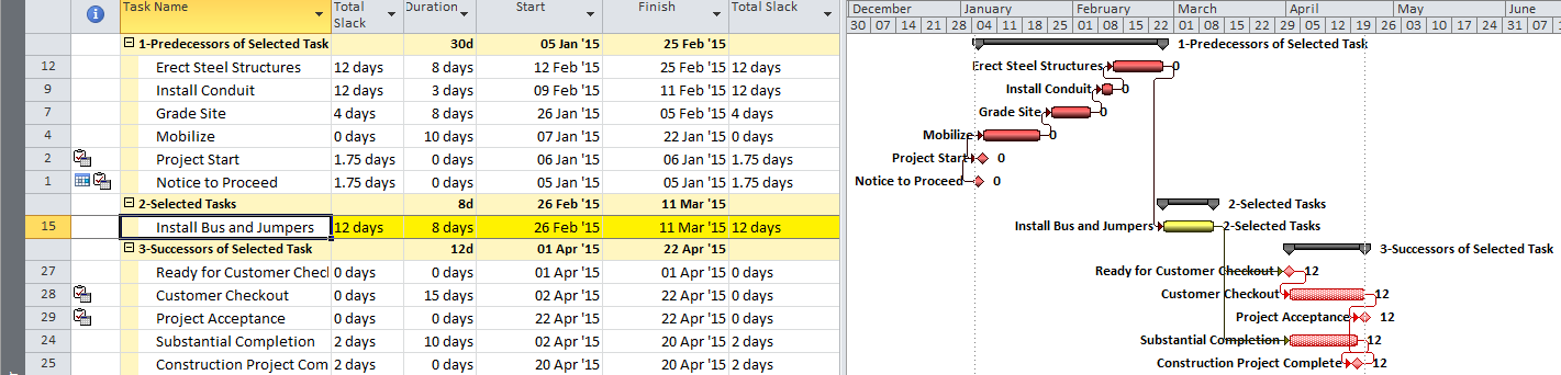
The immediate early-start drivers for summary tasks and subtasks – whether a result of predecessor logic, outline-parent inheritance, or outline-child roll-up – can be identified by the task Inspector as shown in the next figure, and some of these are explicitly enumerated in the “driver” collections of the task. The late-date consequences remain implicit, however.
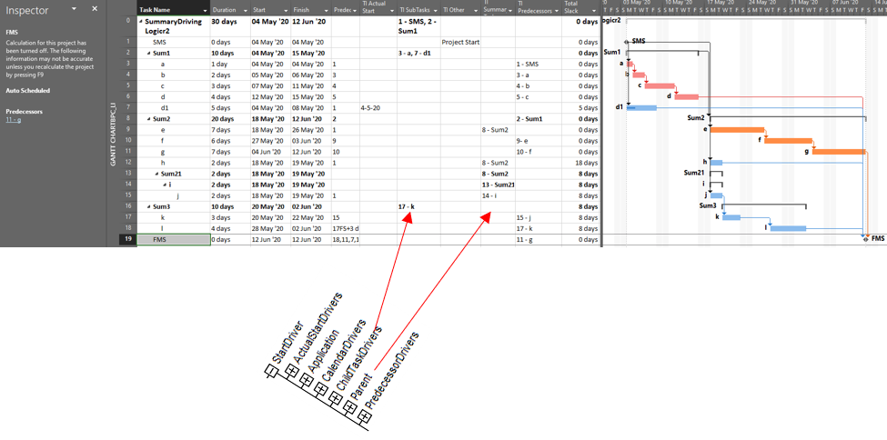
The apparent critical path for the schedule of the previous figure runs through tasks a-d and tasks e-g, including their driving FS relationships. Not shown, however, is the implicit driving FF relationship from task d to its outline parent task Sum1 (here identified in BPC’s logic inspector tool.)
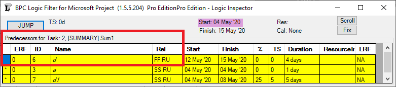
The implicit driving SS relationship from task Sum2 to its outline child task e is correctly identified by the task inspector as well as BPC’s logic inspector.
Those two implicit hierarchical relationships – when combined with the explicit Sum1-to-Sum2 FS relationship – are necessary to properly calculate early and late dates and total slack, which is the source of the critical path depicted. Unfortunately, the built-in tools are not sufficient to fully trace driving logic through such hierarchical relationships, even in this simple schedule.
Neither summary-task relationships nor the consequent hierarchical (parent/child – child/parent) relationships are explicitly recognized in the generally accepted, traditional understandings of logic-based project scheduling – i.e. the critical path method (CPM) and the precedence diagramming method (PDM). Such relationships are not generally supported in other scheduling tools, either, so attempts to migrate MSP schedules containing summary logic into other tools for analysis are typically unsuccessful. It is also clear that adding even a small number of summary-task relationships to a moderately complex project schedule can potentially obfuscate the driving logic paths in the schedule, including the critical path under many circumstances, without fairly sophisticated analysis. Taking these facts together, most project scheduling professionals seem to agree that summary-task logic in MSP represents poor practice and is to be avoided.