An Alternate Approach to Hammock Tasks in Microsoft Project

This entry describes the basis for hammock-type summary tasks and introduces an alternate method (and UpdateHammocks macro) for creating and maintaining such tasks in Microsoft Project (MSP) schedules.

Hammocks and LOE Tasks

“Hammock”* and “Level of Effort” (LOE) tasks in project schedules provide two similar approaches to summarizing and reporting the overall time consumed by a collection of other tasks.  Typically, hammock or LOE tasks are used to represent the indirect management and other support activities associated with the primary tasks, and they are often loaded with management and other indirect resources.  Hammock and LOE tasks are essentially the same, though minor differences exist in the implementation by different software.  Since hammocks and LOE tasks do not possess any driving logic, they should be excluded from any formal definition of the Critical Path for the project.

* The “hammock” name refers to the simple method of suspending a sleeping net or cloth (i.e. the hammock) between two trees.  When first described in hand-drawn activity-on-arrow (AOA) network diagrams, the time-summarizing activity took the shape of a simple curved line slung between two nodes – i.e. a hammock.

Hammocks in Primavera

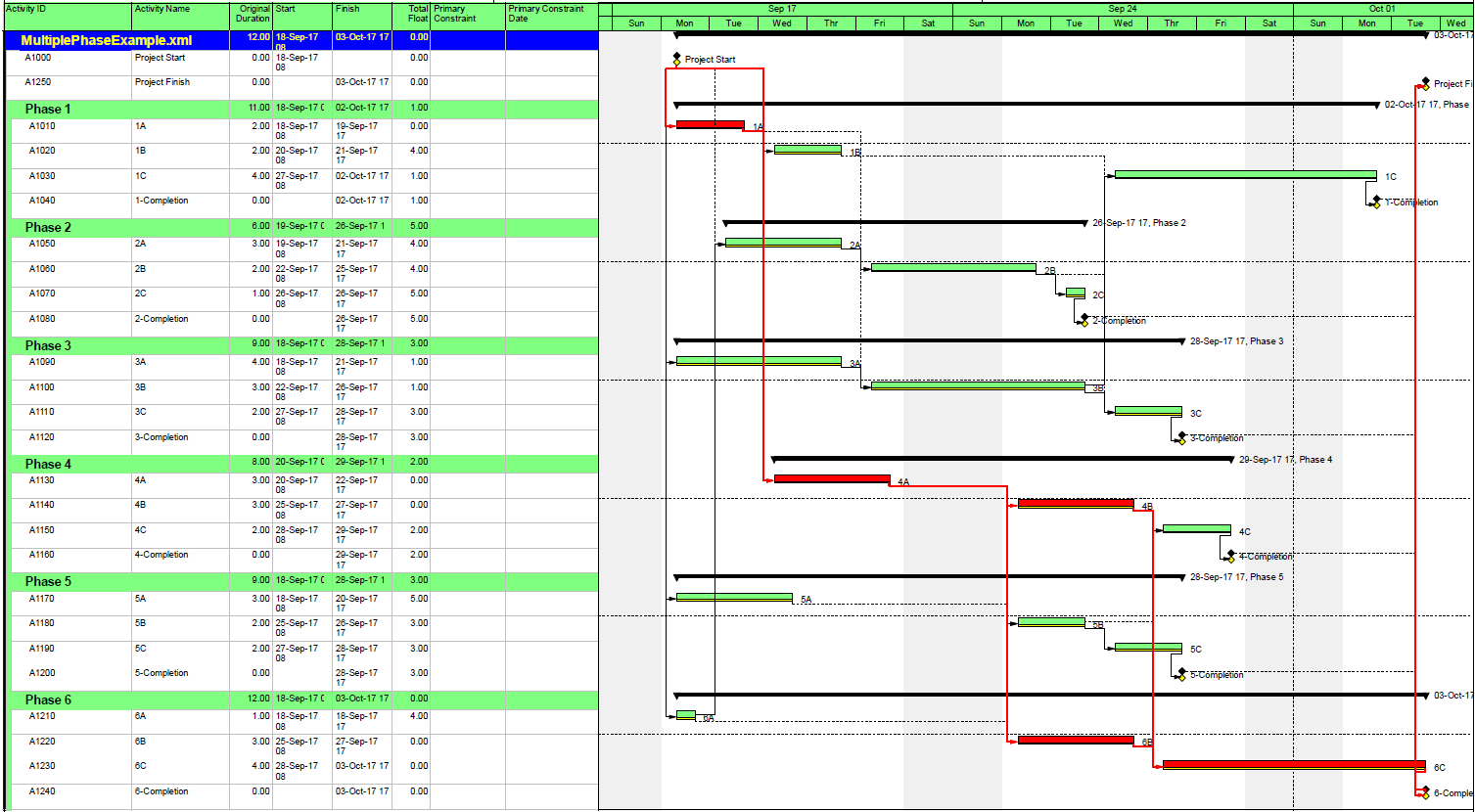
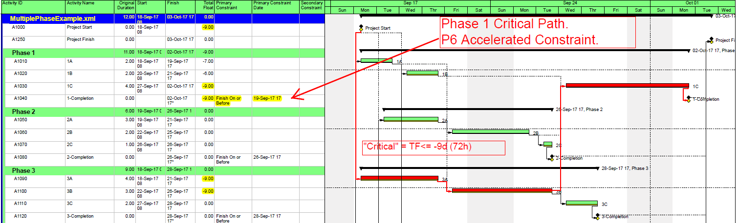
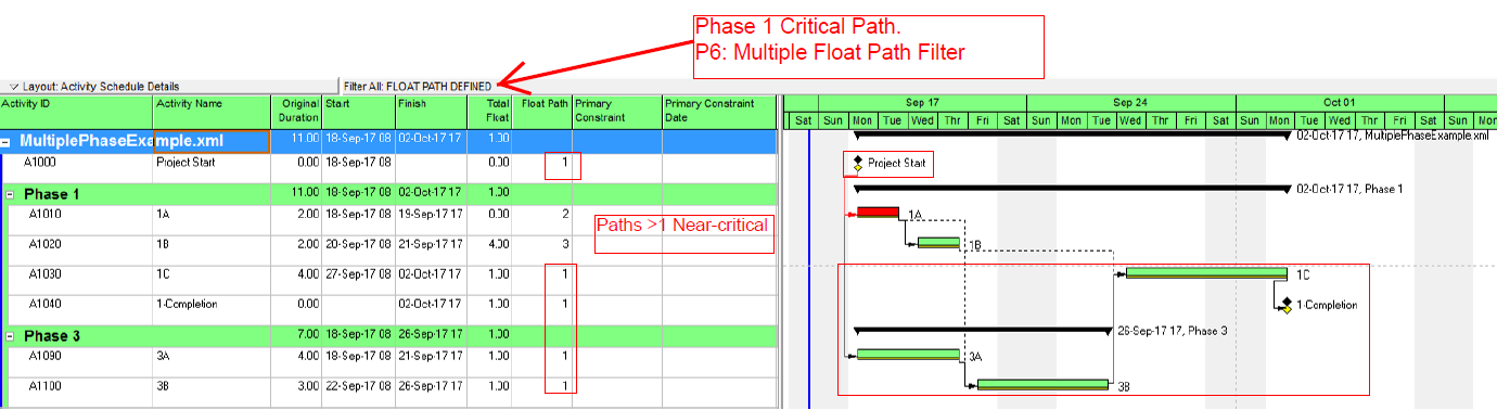
Primavera scheduling tools have long provided explicit activity types for specifying hammock or LOE activities.  Primavera Project Planner (P3) and Primavera SureTrak Project Manager, for example, both included specific hammock activity types that would be specially treated in the schedule calculations.  The start dates for a hammock were defined by its Start-Start predecessors; finish dates came from its Finish-Finish successors; the same activity could not be included in both groups.  Oracle’s Primavera P6, a newer application, allows for LOE activities that inherit their dates from the primary tasks that are included in their “predecessors” and “successors” lists.  They are substantially more flexible than P3’s hammocks.  In most respects the scheduling aspects of these LOE activities are similar to the scheduling of summary bars in P6 schedules (and summary tasks in MSP), with the key difference being that there is no need for common hierarchical structure or activity coding of the related primary activities.

Hammocks in Other Tools

Most other major project scheduling tools also have special-purpose hammock task types.  For example, Phoenix Project Manager, Spider Project, and Deltek Open Plan all provide traditional hammock activity types, whose start and finish are defined by specific logical relationships.  Asta PowerProject also includes a “hammock” task whose construction is more like that of an independent summary activity.  That is, it is not necessary to indicate start/finish relationships.  In general, the number of activities being summarized by the hammocks (or LOEs in P6) are not practically limited.

OLE Hammocks in MSP

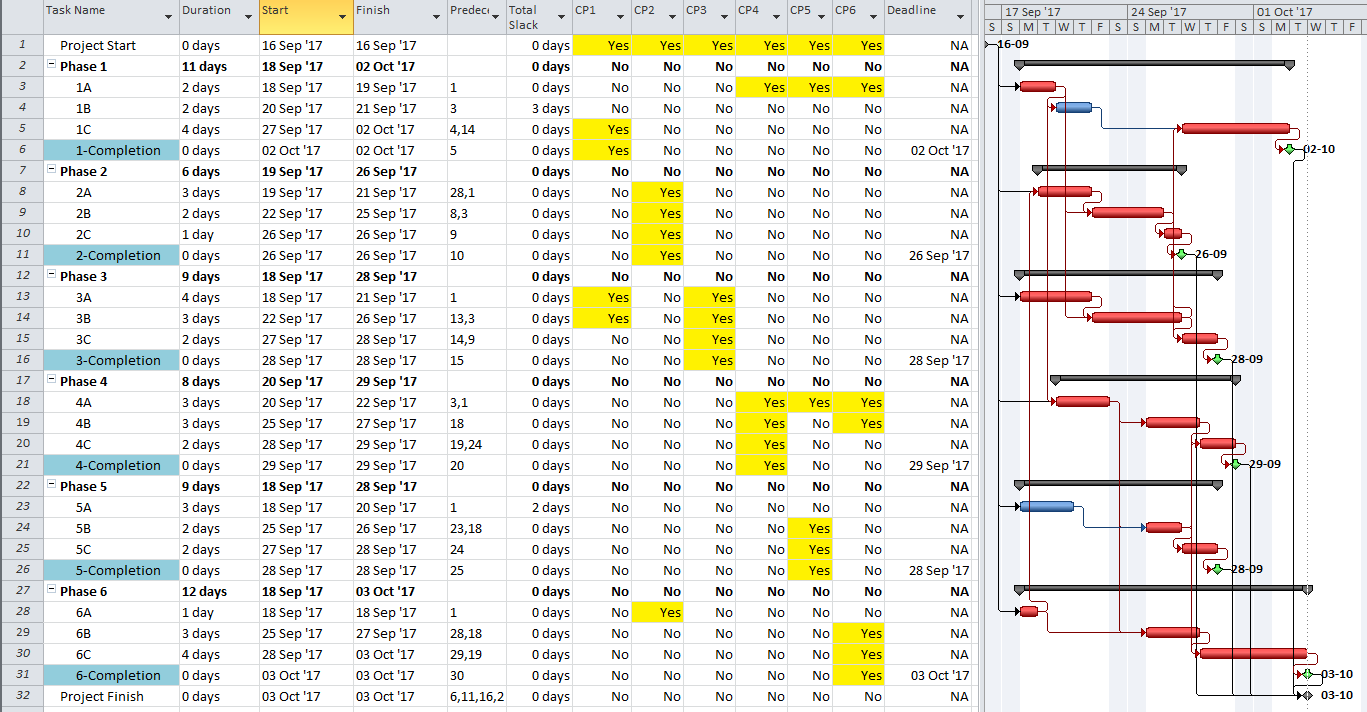
MSP has never included an explicit Hammock or LOE task type, and since summary tasks do not provide the needed solution in many cases, a subtle method for constructing simple hammock tasks was created.  As described here, the method involves copying the start/finish dates from two primary tasks and using a paste-special command to link these dates to the dates of the “hammock” task.  The resulting “links” – based on common Windows OLE (object linking and embedding) technology rather than explicit logical schedule relationships – remain essentially hidden and cannot be easily described or audited in an MSP schedule.

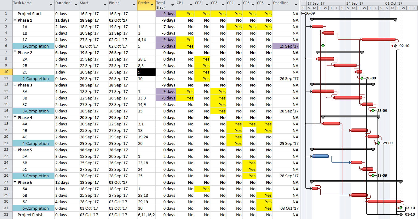
MSP’s response to changes in the linked dates is similar to its response when dates are entered manually: i.e. it sets an early constraint (SNET or FNET) and adjusts the task duration so that the task spans between the two linked dates.  Unfortunately, even if the links remain stable and updated (which is not guaranteed), the sources of these adjustments remain hidden.

MSP OLE Hammock Issues

In addition to the absence of auditable schedule information, regular users of linked hammocks may have noticed the following issues, which are present in MSP Professional 2010 and later releases:

  1. OLE hammocks are limited to summarizing only two tasks, one task providing the start date and the other providing the finish.  This limitation seems most consistent with the original description of hammocks in AOA networks, but it doesn’t exist in other modern software.  Often the activities being summarized are potentially concurrent, and it is preferred to allow the software to select dates from the group.
  2. MSP does not prevent the assignment of additional logical links or other constraints that may conflict with the OLE links.
  3. Creating new linked hammocks by copying and modifying existing linked hammocks – say as part of a fragnet replication – doesn’t work well. The resulting links may be subject to corruption and won’t update reliably.  The only reliable way to create such links is to copy and paste-link them one-at-a-time.
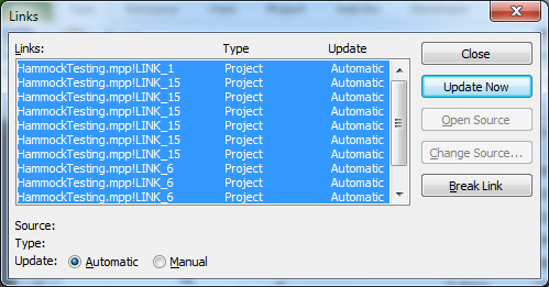
  4. Even “automatic” updating of links sometimes fails, with repeated pounding of the F9 key having no affect. In these cases, it’s useful to open the Links window, select all the links, and force an update. (To open the window, the “Edit Links” command needs to be available on one of the ribbons.  It can be added through the “customize the ribbon” dialog.)  This tool is absolutely necessary to make OLE hammocks even slightly bearable.
  5. Resource leveling of linked hammocks can result in unintended consequences. Although most of these can be corrected by a forced update of the links, some changes require that the hammock task be reconstructed.  E.g. removing leveling splits.  The safest course is to assign a priority of 1000 to all linked hammock tasks, thereby exempting them from any leveling actions.

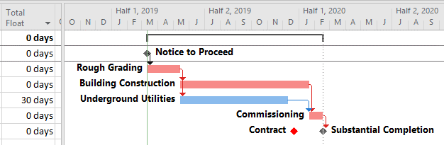
MSP Alternate Hammocks

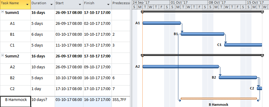
An alternate approach to hammocks in MSP involves the following steps:

  1. Create the proposed hammock task as either a Fixed Units or Fixed Work task, depending on the nature of the resource loading required.
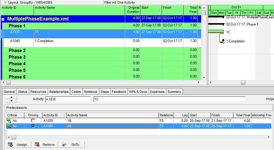
  2. Specify two predecessors to the proposed hammock task: one Start-to-Start and one Finish-to-Finish, without lags. (These are the same tasks that would otherwise be the sources of the Start and Finish paste-links. Here they are visible and auditable. Do Not paste links.)
  3. Avoid specifying any successors to the hammock.
  4. Create a custom flag field named “Hammock,” and assign a value of “Yes” to the Hammock flag for this task.
  5. Adjust the duration of the task such that it spans between the associated start and finish predecessor dates. (This is done automatically with the macro code below.)
  6. Ensure that the task is assigned a Priority of 1000, which prevents it from being resource-leveled. (This is done automatically with the macro code below.)
  7. Load indirect resources to the task as appropriate.

This alternate approach has the key benefit of presenting an explicit logical basis for the hammock task’s schedule dates, which can be easily checked and modified if necessary.  It also supports the use of Fixed-Work hammocks for allocation of fixed contract costs.  While this alternate approach is no more robust than OLE hammocks when summarizing tasks with potential concurrency, it is far easier to review, modify, and update the associated hammock links when the controlling activities change.

The macro/vba code below is intended to automatically update the durations of all hammock tasks in the active project.  It also automatically removes constraints on hammocks and assigns a priority of 1000 to prevent resource leveling.

This macro/vba code comprises a subroutine and a custom function that should be pasted together into a single module in the Visual Basic Editor.  The “UpdateHammocks” macro may then be assigned to a “hotkey” or ribbon command as appropriate.

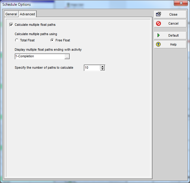
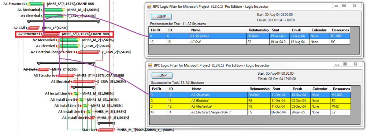
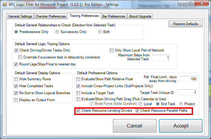
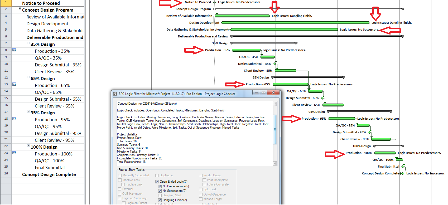
[Edit March 2018.  Our MSP add-in, BPC Logic Filter, excludes Hammocks constructed using this method from Longest-Path and Near-Longest-Path reports.  This satisfies the requirement that such tasks not be included in any calculations of the project’s Critical Path.  Since some users have reported inadvertent introduction of splits into hammock tasks during cost updating, I added a little mini-procedure to close all such splits that are 100% in the future, prior to updating the hammock duration.  I also updated the duration calculator to accommodate an assigned resource with a non-standard calendar.  ]

Sub UpdateHammocks()
'15Sep'17 coded by TM Boyle, PSP.
'A code to routinely update the Durations of unlinked, user-managed "hammock" tasks in Microsoft Project.
'A "hammock" task is an indirect/support task that may be resource loaded.  Its schedule
'depends solely on the tasks that it supports/summarizes.
'For this code to work:
'   - All hammock tasks are coded using a custom Flag field (named "Hammock"); Alternately Flag1 is assumed.
'   - Each hammock task has exactly one or two predecessors:
'       - The "Start" predecessor has a Start-to-Start relationship with no lag
'       - The "Finish" predecessor has a Finish-to-Finish relationship with no lag
'       - If there is only one predecessor, then both start and finish of the hammock will come from it.
'   - Each hammock should have NO successors, although this condition is not enforced.
'       - Successors on the hammock can synthetically lengthen the backward path to its "Start" predecessor,
'           thereby reducing Total Slack in that predecessor and its driving chain.
'[21Mar'18 added code to remove splits in hammocks.]
'[22Mar'18 added code for hammock scheduling using a single resource calendar.]


Dim t As Task
Dim d As TaskDependency
Dim StartH As Date
Dim FinishH As Date
Dim i As Integer 'Added 21Mar'18
        
If Not HammockFieldExists Then
    MsgBox ("Couldn't find a Hammock Flag. Aborting")
    Exit Sub
Else
    'Proceed
End If


For Each t In ActiveProject.Tasks
    If Not t Is Nothing Then
        
        StartH = 0
        FinishH = 0
        If t.GetField(FieldNameToFieldConstant("Hammock")) = "Yes" Then
        'If t.Flag1 = True Then 'Flag1 is used to designate Hammock Activities
        
            'Added 21Mar'18
            'First Close Splits if any
            On Error GoTo 0
            If "Proceed" = "Proceed" Then '(change second "Proceed" to another word to bypass for troubleshooting)
                Do While t.SplitParts.Count > 1
                    i = t.SplitParts.Count
                    'Don't remove any splits that begin in the past
                    If ActiveProject.StatusDate < ActiveProject.ProjectFinish Then 'StatusDate Exists
                        If t.SplitParts(i - 1).Finish < ActiveProject.StatusDate Then Exit Do
                    Else ' Use now date
                        If t.SplitParts(i - 1).Finish < Now() Then Exit Do
                    End If
                        t.SplitParts(i).Start = t.SplitParts(i - 1).Finish
                Loop
            End If
            
            If t.PredecessorTasks.Count = 2 Or t.PredecessorTasks.Count = 1 Then
                For Each d In t.TaskDependencies
                    If d.To = t Then
                        If d.Type = pjFinishToStart Or d.Type = pjStartToFinish Then
                            MsgBox ("Hammocks may only have SS or FF predecessors (Check predecessors): " & t.ID & " " & t.Name)
                        Else
                            If d.Type = pjStartToStart Then StartH = d.From.Start
                            If d.Type = pjFinishToFinish Then FinishH = d.From.Finish
                            If t.PredecessorTasks.Count = 1 Then
                                If StartH = 0 Then StartH = d.From.Start
                                If FinishH = 0 Then FinishH = d.From.Finish
                            End If
                            If d.Lag <> 0 Then MsgBox ("Hammocks should not have lag (Check lag): " & t.ID & " " & t.Name)
                        End If
                    Else
                        MsgBox ("Hammocks should not have successors (Check successors): " & t.ID & " " & t.Name)
                    End If
                Next d
            
                    On Error Resume Next
                        t.Duration = Application.DateDifference(StartH, FinishH, t.CalendarObject)
                        If Err.Number <> 0 Then
                            Err.Clear
                            'Added 22Mar'18 - allow for resource calendar controlling task schedule
                            t.Duration = Application.DateDifference(StartH, FinishH, t.Assignments(1).Resource.Calendar)
                            If Err.Number <> 0 Then
                                Err.Clear
                                t.Duration = Application.DateDifference(StartH, FinishH)
                                If Err.Number <> 0 Then
                                    MsgBox ("Failed to update Hammock (Check predecessors): " & t.ID & " " & t.Name)
                                End If
                            End If
                        End If
                        If Err.Number = 0 Then
                            t.Priority = 1000
                            t.ConstraintType = 0
                        End If
            Else
                MsgBox ("There must be 1 or 2 predecessors for this hammock activity. Not Updating: " & t.ID & " " & t.Name)
                
            End If
        End If
    End If
Next t
Application.CalculateProject


End Sub


Function HammockFieldExists() As Boolean
    Dim StrTest As String
    Dim FlagTemp As String

    StrTest = "Hammock"
    On Error Resume Next
        FlagTemp = ActiveProject.ProjectSummaryTask.GetField(FieldNameToFieldConstant(StrTest))
    If Err.Number = 0 Then 'The fieldname exists and will be used
        HammockFieldExists = True
    Else
        HammockFieldExists = False
    End If
End Function

How to Find Multiple Critical Paths in a Single CPM Schedule

In complex project schedules, multiple critical paths can exist between the project’s start and finish milestones.  Additionally, integrated projects with multiple phased scopes of delivery often have several distinct, contractually-mandated deliverables and corresponding delivery dates.   Each possesses its own critical/driving path.

[Note to searchers: This article has a slight mention of Microsoft Project’s Advanced Calculation Option – “Calculate Multiple Critical Paths.”  It’s near the end, in the section called A Note About Open Ends.] 

A key tenet of the original Critical Path Method (CPM) of project scheduling is that each project has one and only one “Critical Path” (CP) that extends continuously from the project start milestone to the project finish milestone.  The CP is defined by the collection of activities that determine the finish date of the project, such that a delay of any one of them will delay the project.  Traditional methods identify the CP based on Total Slack/Float.  For an elementary review, have a look at The Ultimate Guide to the Critical Path Method over at projectmanager.com.

[As demonstrated in this heavier article of mine, the CP is in many cases not actually defined by the collection of “Critical” activities from the software.]

Single Finish Milestone w/ Parallel Drivers

It is possible for the “critical path” between the start milestone and the finish milestone to have several parallel branches of equivalent length.  These can be described as “multiple critical paths.”

Depending on the details of the schedule model, it is not uncommon to have at least a few activities that are both concurrent and critical.  That is, they comprise parallel branches of a common logic path that drives the completion of the project.  For example, the construction schedule for a residential building may include one activity for “plumbing rough-ins” and another activity for “electrical rough-ins” (where “rough-in” is another term for “first fix” work.)  The two activities have the same driving predecessors (e.g. structural framing) and driven successors (e.g. wall finishes), and they take the same amount of time to complete.  If the wall finishes are on the driving path to project completion, then the two rough-in activities form parallel branches of the “Critical Path” for the project.  Such parallel branches might be repeated for each floor of a multi-story building.  In practice, instances of parallelism/concurrency that comprise only a few activities like those described here seem rarely, if ever, to be identified as “multiple critical paths.”  This is because a) the parallel activities are seen as closely related; and b)traditional methods of identifying and depicting critical activities do not differentiate between the associated logic paths, typically sorting by dates and filtering primarily on the software’s “critical” flag and/or Total Slack/Float.

Multiple critical paths are also created by efforts to accelerate the project completion, such as crashing or fast-tracking exercises, after the initial development of the schedule.  For example, a large scale construction project must be accelerated by 40 days to meet contract commitments.  The critical path of the initial project schedule runs through building construction, while underground utility development activities possess 30 days of Total Float.

Additional resources (and costs) may be applied to compress the building construction activities by 30 days and yield a corresponding acceleration of the project completion.  At that point, the building construction and utility development activities must both be compressed by an additional 10 days (and at additional cost) to obtain the necessary 40-day acceleration of the project.  After the exercise, the building construction and utility development activities are equally driving the project completion, and the schedule possesses two critical paths.

Further crashing or fast-tracking exercises may add more critical paths.  The associated activities all possess the same total float/slack, and all are marked as “critical.”  Differentiating between the various paths requires a method for separately tracing and coding driving logic, either analytically or by visual inspection.  Such methods are explored later in this article.

In practice, multiple critical paths are also created during project execution, as float is completely consumed by unplanned delays in activities that were previously non-critical.  Exploration of such delays will have to wait for another article.  (Notions of the “Critical Path” are sometimes suspended in the late stages of major/mega projects, as virtually every incomplete activity may delay the ultimate completion of the project and is therefore “Critical”.)

Ultimately, all three of these instances of multiple critical paths can be traced to a certain simplification (or presumed simplification) of resource utilization in the project.  In the first example, plumbing and electrical crews are presumed to have exactly the same productivity, resulting in the same duration for both activities.  In fact, one of the crews may be capable of completing the work sooner but paces its effort in order to match the scheduled duration.  In the second example, it is presumed that the building construction activities and utility development activities may be compressed by exactly 40 days and 10 days, respectively.  In fact, optimum resource usage often follows a step-wise rather than linear (or even continuous) function; consistent with adding discrete crews or substituting higher-capacity equipment.  Thus, the building construction may be optimally compressed by 35 days or 45 days (not 40 days), and the utility development may be optimally compressed by 9 days or 12 days (not 10 days).  As a result, the project completion is optimally accelerated by 42 days (not 40 days), with the critical path being governed by utility development.  The crashed building construction activities get 3 days of float.

When taken to this level of detail, a single critical path may indeed be re-established.  Depending on the needs of the project, such detail may or may not be justified in light of various project uncertainties and the increased management effort involved.

Multiple Delivery Milestones

When a project involves the parallel or interim delivery of multiple scopes of work, each delivery may be construed to have its own “critical path”  – i.e. the sequence of activities and relationships determining the delivery date for the particular scope of work.  More importantly, any particular activity in the project schedule may be expected to participate in more than one of these multiple critical paths.  Examples include design, setup, or testing activities that may be common to several deliveries.

Here is a simple example project comprising six “phases” of inter-related tasks in a Microsoft Project (MSP) schedule.

MSP identifies the CP for the project on the basis of Total Slack (TS<=0), and it colors the associated bars red.  The table includes six columns identifying the critical/driving tasks for each of the phase-completion milestones (CP1 through CP6).  For example, the critical/driving tasks for the Phase 1 Completion (ID #6) are flagged “yes” and highlighted yellow in the CP1 column.  This path comprises the following sequence, which is easily verified by inspection: 1->13->14->5->6.  Interestingly, the first Phase 1 task — ID #3 – “1A” —  is marked “critical” for the overall project but is not critical for the Phase 1 Completion.  A delay of this task would delay the project but would not immediately delay Phase 1.  Coincidentally, since Phase 6 is the last phase to finish, its critical path (column CP6) corresponds to the critical path for the overall project – i.e. the red bars and TS=0.

The project is scheduled identically using Oracle Primavera P6 (P6).

As a result of the modest number of inter-phase relationships, the critical/driving paths for five of the six phases include activities from other phases.  The exception, Phase 3, is essentially self-contained, although several of its tasks are also driving the completion of Phase 1.

So, how are these six different critical paths identified?

Identifying Multiple Critical Paths

There is in fact no way to simultaneously define the critical paths to each of the six phase completion milestones of the example project using Total Slack alone without manipulation.  The paths must be identified individually and directly reported (in the manner of BPC Logic Filter) or manually marked.

Deadlines / Late Constraints

It is common to apply deadlines (or late constraints in P6) to key completion milestones that are contractually defined – typically with financial consequences for delay.  Deadlines have the potential to reduce Total Slack/Float, which MSP and P6 use to identify Critical tasks.  When deadlines are applied to tasks and milestones that – together with their predecessor chains – are logically and organizationally separate, then Total Slack/Float can provide a reasonable indication of the driving path to each “deadlined” task or milestone.  This is a rare circumstance.  With only a single deadline applied, the Total Slack/Float for any task will be potentially influenced by the Project Completion date and by the deadline date, with the more “urgent” of the two forcing a lower Total Slack/Float value.  With more deadlines and intersecting logic paths, the issue is multiplied.

In the present example, each phase completion task has been given a deadline corresponding to its current finish date.  Consequently, all except two tasks in the entire project are given a Total Slack value of Zero and marked “Critical.”  The delay of any of these tasks is certain to violate at least one of the deadlines, although the deadlines to be violated are not obvious without the table.  The actual driving path to each phase completion remains obscured.  Although not completely reliable for defining individual driving paths, deadlines (and late constraints in P6) remain useful for flagging those tasks whose delay could affect (or already have affected) a contractually significant milestone.

If the project already includes multiple deadlines (for contractually significant milestones), then the critical/driving path for each milestone can be identified (one at a time) by forcing the milestone onto the MOST critical path, i.e.:

  • Temporarily accelerating the deadline date to the point that it becomes the most “urgent” deadline in the schedule network for all affected tasks.  The Total Slack of the milestone and its driving predecessors is then easily distinguished from that of other tasks; and then
  • Marking the tasks identified by the lowest Total Slack value.  Here, the deadline for the Phase 1 completion was accelerated by 9 work days, resulting in a Total Slack of -9 days for the completion task and its driving predecessors.  The CP1 custom flag field could then be marked accordingly.

As shown here, a nearly-identical process (using an accelerated Finish-on-or-before constraint) can be used for a P6 project schedule with multiple late constraints.

A similar approach can be used by adding a deadline or late constraint (in P6) if the project has none.

In fact this is the “Constraint Method” that was recognized by the Defense Contract Management Agency (DCMA) as the only valid method for defining a program critical path as part of its 14-point schedule assessment.

As shown above, using deadlines or constraints to generate negative slack/float is an effective way to identify multiple critical paths.  In Microsoft Project, however, these paths are difficult to distinguish on the Gantt charts because their red bars are not uniquely differentiated from others.  Both MSP and P6 can set the “Critical” flag – resulting in the red bars – for any tasks whose Total Slack/Float is below a certain user-specified threshold.  Unlike P6, MSP does not permit this threshold to be less than zero.  Consequently, all tasks with negative Total Slack – even those which are not driving anything – are flagged as “Critical” and given the red bar in MSP.

Trailing Dummy

An alternate approach to overcome this limitation for presentation purposes uses a “super-long trailing dummy” task.  In this approach, all deadlines and late constraints in the project must be removed (at least temporarily).  Then a “trailing dummy” task is assigned as a successor to the first key completion milestone, forcing the milestone onto the critical path.  The duration of the trailing dummy must be long enough to extend the completion of the project, creating positive Total Slack for all tasks that are not part of the dummy’s driving predecessor chain.  As shown in the following two figures, adding the 100-day Trailing Dummy task as a successor to the Phase 1 completion milestone effectively creates a new critical path for the project – one which is easily recognized as the Phase 1 critical path on the Gantt chart.  Moving the trailing dummy successor from phase to phase – one at a time – reveals the unique critical path for each phase.  

So far all of these approaches rely on temporary manipulation of Total Slack or Total Float, and it is important that such temporary changes be reversed prior to sharing or distributing schedule files.  Obviously, these approaches can be labor-intensive and error-prone, making them impractical when the schedule status (and logic) is in flux – as during regular weekly/monthly updating.  Even when the complications of multiple deadlines or late constraints are removed, Total Slack also becomes unreliable as an indicator of critical/driving relationships whenever multiple task/resource calendars or resource leveling are applied.

Driving Logic Tracing

The “Longest Path” algorithm in P6 defines the project’s Critical Path by automatically tracing driving logic backward from project completion.  This avoids the complications that late constraints and multiple calendars introduce to the interpretation of Total Float, and it is the preferred calculation method when these factors exist.  (It is unfortunate that P6 seems to be the only mainstream project scheduling tool to implement it.)  Since the algorithm always begins the backward trace with the project completion activity, using it with the trailing dummy method above is useful for identifying multiple critical paths on the basis of driving logic.  Driving logic can also be traced in other ways.

Driving Path Trace / Filter (P6)

P6 automatically identifies driving and non-driving relationships in the task details.  It also allows users to automatically add activities to existing filters by simply selecting them.  The combination of these two features allows users to manually construct a filtered view of the critical path to any completion milestone by simply clicking backward through the driving relationships.

The first step is to construct a custom filter to isolate the completion milestone of interest.  Here we are focusing on the Phase 1 completion milestone.

Next, the chain of driving activities (i.e. the driving path) is added to the view by stepping backward through the driving relationships using the “GoTo” button in the predecessors pane.  Here is the view after taking the first backward step.

Here is the view after tracing the network all the way back to the first driving relationship.  This is the driving (i.e. “critical”) path for the Phase 1 completion milestone. 

This click-tracing technique can become tedious when the project schedule is complex and there are numerous branches to the logic paths.  For example, if an activity along the driving path has two driving predecessors, then the analyst must make a note to return to the second one after the first is fully explored.  In addition, P6 routinely marks all links to Level-of-Effort (LOE) activities and links to ALAP-constrained predecessors as driving.  The LOE activities must be ignored during the trace, and the ALAP constrained activities need to be evaluated separately.  Finally, near-driving logic paths can be identified by the “relationship free float” field in the predecessors table, but isolating driving and near-driving paths involves creating and marking a number of new activity fields.

Fortunately, P6 includes an advanced scheduling option for calculating multiple float paths, which I’ve previously written about here.  This option effectively automates the click-tracing technique.

Combined with a view/layout/filter that depicts the “Float Path” field, this option provides a robust and repeatable method for defining the driving and near driving paths to each phase completion milestone in a P6 schedule.  (The “free float” option must be used.)  Float Path number 1 identifies the (first) driving path.  Higher Float Path numbers identify any parallel driving paths and near-driving paths.  Like the click-tracing technique, Multiple-Float Path analysis works without modifying the schedule network, so reversing temporary changes is not a concern prior to sharing the schedule.  Neither of these techniques affects P6’s assignment of the “critical” flag, however, so red-bars on the Gantt charts are not meaningful.

Task Path (MSP)

If you are using a recent version of Microsoft Project (2013+), then the driving path to each phase completion milestone can be visually identified and highlighted on the bar chart using the “Task Path” function with the “driving predecessors” switch selected.  (Task ID6 is selected, and the tasks in its “Driving Predecessors” Task Path are highlighted orange.)  The user can then manually enter a code (like the custom flag fields shown above) to mark the highlighted tasks.  It is fairly straightforward to automate the generation of a task path filter using a macro, and some macro snippets have been published.  (E.g. here.)  Unfortunately, Task Path’s “Driving Predecessors” are not reliable for most complex projects (e.g. when non-Finish-to-Start links, in-progress tasks, or manually-scheduled tasks are present.)  Those issues are discussed in my other blog entry here.

Logic-Tracing Add-ins

BPC Logic Filter (an MSP add-in) was developed in part to offset the absence of the Longest Path and multiple float path analysis in MSP.  The chart below shows driving and near-driving paths to Phase 1 completion – depicted by altering the bar chart.  The driving path is indicated by dark red bars with the zero indicating zero relative float.  Consistent with the trailing-dummy results, the two non-driving tasks that are part of Phase 1 are depicted as having 2 days and 3 days, respectively, of float relative to the Phase 1 completion milestone.  That is, they could slip 2 or 3 days before affecting the milestone.  Similar depictions of the driving and near-driving paths for the other five phases, and for the project as a whole, are made possible with a few clicks.  Since the schedule network is not manipulated in any way, Total Slack remains unchanged, and there is no need to reverse any analysis-based modifications prior to sharing the data file.

[See also Multiple Critical Paths – Revisited with BPC Logic Filter]

A Note About Open Ends

Some experts have suggested using open-ended logic along with a built-in software calculation setting to automatically mark multiple critical paths.  The proposal is as follows:

  1.  Ensure that each of the Phase completion milestones is sequenced so that a) it is a logical successor to all the activities in the phase, and b) it has no successors.
  2. Enable a calculation setting that forces activities with no successors to have zero total float.  In P6, this setting is the “Make open-ended activities critical” schedule option.  In MSP, the setting is the “Calculate multiple critical paths” advanced calculation option.

Effectively, this is the same as assigning a deadline to each completion milestone at a date that exactly equals its early finish date – an example of which was already explored above.  It is subject to the same drawbacks of that approach, but with none of the advantages.  I.e. If there are intersecting logic paths between phases (as shown in the example), then which activities are driving which milestone cannot be determined based on total float alone.  One merely sees a bunch of zero-float activities in all the phases.  Moreover, the basic technique of accelerating the milestone’s deadline/late-constraint date to reveal its driving predecessor path (through negative float) is not available when no deadline or late constraints have been applied.  Between this and other failings, I just don’t see any advantages to this open-ends approach.

Recap

A project schedule can possess multiple critical paths for one of two primary reasons:

  1. There is a single key completion milestone at the end of the project, and multiple, concurrent, parallel driving paths to that milestone exist.  In this case, the multiple critical paths often reflect a schedule model that is simpler than the actual execution of the project.  Correctly accounting for productivity of the assigned resources may remove the apparent concurrency and restore the single Critical Path, but the increased overhead of developing and managing a more detailed schedule would need to be justified.
  2.  The project possesses multiple key completion milestones, each with its own legitimate driving/critical path.  In this case, the correct identification and status reporting for the multiple Critical Paths is often beyond the capabilities of the scheduling software.  Then specialized logic tracing techniques are required.

These factors can also be combined in some project schedules.

Inspecting Task Resource Drivers with BPC Logic Filter for Microsoft Project

BPC Logic Filter – an add-in for Microsoft Project (desktop) – includes an advanced Logic Inspector feature to greatly simplify the examination and navigation of resource-leveled, logic-driven schedule activities.

The resource leveling feature in Microsoft Project (MSP) offers an effective method for management of resource-constrained projects, but most project managers don’t appreciate its impact on Total Slack, the Critical flag, and the resulting “critical path.”  Specifically, all of those terms become unreliable or misleading in the presence of resource leveling.  I first wrote about those issues here.

With some improvements to BPC Logic Filter – we were able to identify resource-driving links and include them in The Resource-Constrained Critical Path and in other logical path analyses.

Analyzing logical paths in schedules requires detailed examination of each task’s dependencies and (for leveled schedules) resource assignments. It’s helpful to have the results of such examinations at hand while reviewing (and confirming) the logical path analyses, so recent versions include a task Logic Inspector for Inspecting Task Links with BPC Logic Filter.

Logic Inspector also includes inferred resource-driving links if desired by the user.  Consider this simple resource-leveled schedule from the earlier articles.

With resource-checking disabled (and no calendars or constraints to confuse things), BPC Logic Filter computes relative float and identifies driving predecessors in a way that is consistent with MSP’s calculation of total slack.  For the A2 Structures task (ID 11), this means that the driving predecessor is the only predecessor — ID10: A2 Civil — even though it finishes two weeks before A2 Structures starts.  It also means that A2 Structures is logically driving all three of its successors.

Adding the late-relative float (LRF) column identifies the one successor relationship with bi-directional driving logic.  Thus, ID14: A2 Electrical Change Order 1 is highlighted red as the successor relationship with the most effect on the total slack of the selected activity. 

While this method is useful for understanding how MSP computes slack in resource leveled schedules, it does not help in understanding the actual resource limitations that drive the schedule of a task.  To gain that understanding, we first visit the Tracing Preferences tab in the Settings and ensure that Resource Checking is enabled.

Now Logic Inspector shows us the true picture of the schedule of the A2 Structures task.  Namely:

1. A new predecessor — the true driving predecessor for the task — is identified: the A1 Structures task in Area 1 must finish (and release its resources) before the A2 Structures task can start.  The only explicit logical predecessor of the A2 Structures task — ID10: A2 Civil — has 10 days of relative float.  That is, it could slip two weeks according to the standard calendar before THIS RELATIONSHIP starts to drive the A2 Structures task.

2. A new “driven successor” is identified in that the A3 Structures task may not start until the structural resources are finished with A2 Structures.

3. The A2 Electrical Change Order 1 task (ID14) is actually 40 days (8 weeks) away from being driven by its relationship to the current task.  (It is in fact driven by other resource constraints.)

4. Tasks 10 and 14 remain highlighted as late-date drivers.  With no direct impact on the scheduled dates for the selected task, they illustrate MSP’s basis for total slack calculations.

The JUMP button — which allows on-the-fly exploration of the schedule through logic links — treats the (implicit) resource driving links the same as explicit logical relationships.  Consequently, it is just as easy to hop through the logic of most resource-leveled schedules as it is to hop through one with no resources at all.

Dangling Logic in Project Schedules

Logic Driven project schedules can suffer from two kinds of open-ended or Dangling Logic, which makes the resulting schedule unreliable for dates or float analysis.

Project schedules need robust logical bases to reach two primary objectives:

  1. A schedule that accurately represents a true and achievable plan for executing the work – including technological and resource constraints.
  2. A schedule that supports accurate forecasting of consequences when the work does not proceed as originally planned – for example when activities fail to start or finish on time.

Dangling Activities – CPM

Logic-driven scheduling – often generically identified as “Critical Path Method” (CPM) scheduling – determines schedule dates by enforcing stringent logical sequential relationships between tasks from the start to the finish of the project.  The definition of adequate scheduling logic depends on the details of the project.  Logic is clearly inadequate, however, if any activity in the schedule is left logically disconnected from either the project start or the project finish – i.e. the activity is left “dangling.”  In the simple network diagram shown below, four activities are shown with no predecessors, while one activity is shown with no successors.  These cases typically represent omission of legitimate logical relationships with other (latent predecessor/successor) activities.  As a consequence, the early and late dates – and the Total Float – of all potentially-connected activities are not reliable.  The objectives of the logic-driven schedule can’t be met.  As a general rule, every activity in any CPM schedule – except the start and finish milestones – must have at least one predecessor and at least one successor.  Dangling activities not meeting this rule – also known as open-ended activities, “hanging activities”, or simply “hangers” – indicate inadequate schedule logic.

Dangling activities that are missing predecessors and/or successors are relatively easy to isolate in project scheduling tools – including Microsoft Project (MSP) and Oracle Primavera P6 (P6) – by using an activity filter that searches for empty “predecessors” or “successors” fields.  It is common for experienced schedulers to routinely tie such dangling activities to general-purpose milestones such as “notice to proceed” (as a predecessor) or “substantial completion” (as a successor).  Such an approach removes the obvious indication of inadequate logic.  Close review of the relationships at such “merge points” in the schedule may still be necessary to identify activities whose true predecessors and successors are not sufficiently defined.

Dangling Activities – PDM

Most modern scheduling software implements a variation of CPM scheduling called the Precedence Diagramming Method (PDM).  In addition to the “Finish-to-Start” relationship of basic CPM scheduling, PDM allows “Start-to-Start,” “Finish-to-Finish,” and “Start-to-Finish” relationships, all with or without lags.  While PDM software allows more realistic and more efficient modeling of real-world project schedules, it is possible for activities to have both predecessors and successors yet still suffer from dangling – hence inadequate – schedule logic.  These cases – generally categorized as dangling finish and dangling start – are also known as “orphan relationships.”

Dangling Finish

Consider the following three activities taken from a conceptual schedule for a civil construction project.  The project will take place on land that has been intentionally surcharged (pre-loaded with piles of soil) to strengthen the underlying materials.  The conceptual plan for the three activities is simple: 1) Push/roll-off the surcharge material to adjacent areas; 2) Perform grading and quality-assurance testing of the ground; 3) Construct concrete foundations for the buildings.


Because these activities are spread over a large area, it is possible to start the grading before completing the roll-over and to start the foundations before completing the grading.  The scheduler has modeled these relationships (in MSP) as SS+50% – that is the successor may start only after the predecessor has started, but with an additional lag of 50% of the predecessor’s duration (computed according to the successor’s calendar).  These activities, relationships, and the resulting (early) scheduled dates seem to reflect a true and achievable plan for prosecuting the work, meeting the first objective of a logic-driven schedule.

If the activities fail to progress as initially planned, however, then the schedule may not accurately forecast the consequences.  If the Roll-Over takes longer than expected, then this delay may in fact affect completion of the Rough-grading task and, eventually, the foundation construction and its successors.  The schedule model fails to account for these extended finishes, however, and may forecast outcomes that are physically impossible – such as building foundations being constructed in areas where the surcharge material has not yet been removed.

When the indefinite delay of an activity’s finish has no logical consequences for any other activity, then the activity has a “dangling finish” – representing incomplete logical development of the schedule.  In a PDM schedule, any activity with ONLY SS or SF successors has a dangling finish.  Such dangling finishes are called “open finishes” in Acumen Fuse, a 3rd party diagnostic tool.

Dangling Start

The same three activities could be modeled instead using Finish-to-Finish relationships to arrive at identical dates.

If subsequent schedule developments lead to longer durations for successor activities, the schedule model will respond by having them start earlier.  As a consequence, some schedule dates may occur at times that are physically impossible – such as starting rough grading before the first shovel of surcharge has been removed or (again) building foundations being constructed in areas where the surcharge material has not yet been removed.

When the indefinite acceleration of an activity’s start may be implemented without logical restraint from any other activity, then the activity has a “dangling start” – representing incomplete logical development of the schedule.  In a PDM schedule, any activity with ONLY FF or SF predecessors has a dangling start.  Such dangling starts are called “open starts” in Acumen Fuse.

Correction of Dangling Starts/Finishes

The examples shown are typical of overlapping activities with progressive feed relationships.  In such cases, it is common to implement a “ladder logic” scheduling model, where multiple parallel Start-to-Start and Finish-to-Finish relationships are imposed between related activities.  Such a model is easy to implement in P6.  In MSP – which prohibits parallel relationships between tasks – then dummy milestones are needed.

In a schedule model incorporating ladder logic, one of the two parallel relationships will drive the successor’s dates, depending on the relative durations and lags.  In the example below, the Rough grading activity is driven by its Start-to-Start relationship with Roll-over.  Because Rough grading has been extended, however, the subsequent Foundations construction is delayed (and driven) by the Finish-to-Finish relationship from Rough grading.  This represents robust logic development between the activities.

In general, dangling starts/finishes are avoided by explicit inclusion of all legitimate technological and/or resource constraints in the schedule model, even where the resulting relationships are not obviously driving successor activities.  This is, of course, the basis of all robust logic-driven scheduling practice.

Finding Dangling Starts/Finishes

Until recently, detecting and isolating dangling starts and finishes was not an easy process for users in either MSP or P6.  In both tools, the preferred approach is to specify an activity/task filter to show only those activities that:

  • For Dangling Starts –
    • Have some predecessors, and
    • Have NO FS or SS predecessors.
  • For Dangling Finishes –
    • Have some successors, and
    • Have NO FS or FF successors.

In MSP, each task includes a “predecessors” field listing the Task ID, relationship type, and lag for each predecessor relationship.  The task “successors” field lists the same information for successor relationships.  Unfortunately, the default relationship type – FS – is not explicitly listed in either field, and preparing a filter to exclude activities that contain FS relationships in one field or the other is not trivial, requiring several intermediate calculations.  Alternately, the user is left to manually inspect the predecessors and successors of each task, to export the project to Excel for analysis, or to use an add-in like Acumen Fuse or BPC Logic Filter to identify danglers.  [The add-ins examine the underlying relationship objects in the MSP database, which could also be done directly using a Project macro/vba.]

Similarly, each activity in a P6 schedule includes both “Predecessors” and “Successors” list fields, but these lists include only the IDs of the connected activities – relationship types are excluded.  P6 16.1 and later releases include two additional fields – Predecessor Details and Successor Details – that include relationship types and may be easily included in a filter specification using the above criteria.  Users who have not updated to P6 16.1 or later – and who do not have access to an add-in like Acumen Fuse or Steelray – may export the activity and relationship information to a spreadsheet for analysis.  (Spreadsheet analysis of the P6 data is generally more straightforward than for MSP.)

Consequences of Dangling Logic

The primary consequence of dangling logic in a project schedule is an initial/Baseline plan that is not reliable due to the omission of substantial sequential constraints.  For example, many fast-track design-build projects require the start of field work before the completion of engineering, and sometimes the final engineering works are either left dangling or are tied only to a generic project completion milestone.  The logical ties between certain engineering activities and the necessary quality assurance and commissioning activities may be inadvertently omitted.  Without complete logic, neither the early (CPM) dates nor the late dates for the project are reliable.  Total Float shown for the later engineering activities and for their latent/unlinked successors may be excessive.  Since Total Float and the Critical Path definition are unreliable as a result of missing logic, the Baseline project schedule does not provide a suitable basis for monitoring progress or for evaluating potential delays.

Many project schedules may appear acceptable at the time of Baseline review, but dangling starts and finishes can severely compromise their usefulness during the project execution.  This is ultimately because actual durations invariably differ from baseline durations, but the secondary relationships that are needed to ensure logic integrity are missing.  In other words, the schedule model fails to reflect the real consequences of activity delays that appear during schedule updates.  The flaws in the schedule logic become obvious, and credibility is lost.

Schedule Risk Analysis is aimed at quantifying, typically through simulation, the consequences of uncertainty in schedule durations.  Since the intent of a simulation is to repetitively reproduce the consequences of changed durations in the schedule, the model weaknesses that affect the schedule update process also affect the outcome of the simulation.  Therefore, risk simulation of a project schedule with dangling logic is not reliable.

Terminology for Dangling Logic

Dangling logic – and particularly dangling starts and finishes – have been identified as such in the literature for at least 10-15 years.  See http://www.projectrisk.com/white_papers/The_Problem_with_Dangling_Activities_in_Project_Schedules.pdf.

Although the two concepts of dangling logic described here (i.e. the CPM and PDM varieties) are fairly straightforward, there is not uniform agreement on the terminology.

The Practice Standard for Scheduling, Second Edition (2011), published by the Project Management Institute (PMI) limits its “dangling” logic discussion to the PDM variety.  It describes “dangling” activities as activities that don’t “have an FS or SS predecessor and an FS or FF successor.”  In this standard, “Open-Ended Activities” include those “lacking either a predecessor or a successor or both.”  Thus, while not explicitly stated, “Open-Ended Activities” are a subset of dangling activities.

PMI’s Scheduling Excellence Initiative Committee has described a dangling activity somewhat vaguely.  The Committee’s CPM Scheduling for Construction: Best Practices and Guidelines (published by PMI, 2014) provides the following definition – “Dangling Activity: An activity tied from only one end (start or finish). A dangling activity has only a predecessor(s) or successor(s), not both.”  This definition clearly combines the two concepts without distinguishing between them.  “Dangling” references in the text are limited to the CPM, or open-ends, concept.

CPM in Construction Management, Eighth Edition (2016), a graduate-level textbook and respected reference book for serious construction planners and schedulers, contains only a single reference to “dangling activities” as something to be precluded.  It does not otherwise describe or define them.  The book briefly discusses dangling starts/finishes as a problem unique to PDM schedules, but it uses the term “orphaned relationships” rather than “dangling”.

The US’s Government Accounting Office (GAO) and Defense Contract Management Agency (DCMA) both align with the PMI practice standard, describing dangling activities according to the PDM concept.  From GAO-16-89G, Schedule Assessment Guide; Best Practices for Project Schedules (2015) – “Dangling activities: number of remaining detail activities and milestones with no predecessor on start date” and “Dangling activities: number of remaining detail activities and milestones with no successor off finish date.”    (As of the 21Nov’09 revision, DCMA’s 14-Point assessment guidelines provide comparable definitions and a “general rule to avoid Dangling Activities” under Metric #1: Logic.  They are NOT explicitly included in the metric, however.)  Open-ended logic (i.e. the CPM variety of dangling logic) is simply identified as “missing logic,” “missing predecessors,” or “missing successors.”  This is the source of DCMA’s Metric #1.

The Planning & Scheduling Excellence Guide (PASEG v3, 2016), published by the National Defense Industry Association,  includes a brief section on Open Ended Tasks among things to avoid in its chapter on Horizontal Traceability.  This section mentions “dangling logic” (specifically a dangling finish) as something to be avoided because it invalidates schedule risk assessment.  Neither term is formally defined in the guide.

AACE International (formerly the Association for the Advancement of Cost Engineering) publishes a number of recommended practices (RPs) related to project scheduling.  Unfortunately RP 10S-90: Cost Engineering Terminology (which is routinely updated to reflect the development of related standards and RPs) includes a definition for “Open-Ended Activities” only.  It ignores dangling logic of the PDM variety.

Dangling Logic in BPC Logic Filter

Users of BPC Logic Filter for Microsoft Project can execute the Project Logic Checker to isolate dangling logic and other issues affecting project schedule integrity.  The PMI/GAO definitions are used.  This figure shows the same schedule depicted in the network diagram at the beginning of this post – after running the Project Logic Checker.  The five “No Predecessors” and two “No Successors” tasks (including start and finish milestones) are clearly tagged and summarized, as are two dangling-finish tasks.