Troubleshooting Circular Task Relationships with BPC Logic Filter

Planners attempting to build complex project schedules in Microsoft Project will typically come across the circular logic warning at some point when trying to link tasks.

In general, most such messages come from assigning logic to summary tasks, which experienced schedulers don’t do.

When an experienced scheduler encounters the circular logic warning, it often means that he has made an earlier error in the logic that is only now being detected as the loop is closed.  For example, a normal construction “fragnet” for concrete structures may include the following task sequence: Form -> Pour -> Finish -> Cure – > Strip(forms), repeated over and over for different structures on the project. If I get the warning when trying to impose one of these obvious links – say from Pour to Finish, then I know that Pour and Finish are already connected.  I have to find the logical error in that path of task connections.

Fortunately,  BPC Logic Filter includes a little feature that’s been variously referred to as “Bounded Network Analysis,” “Truncated Logic Tracing,” and “Logic Tracing to Target.”  It finds all the connections between any two tasks in the project and filters out all the others.  This makes finding the error that much easier.  The figure below highlights the selected task (Form3) in yellow and the target task (Pour3) in orange.  In the example, I can trace the problem linking Form3 and Pour3 to a “dummy string” of tasks that was inserted between Cure3 and Cure2.

Early last year I wrote about a method for finding the connections between two arbitrary activities in a CPM schedule.  Most of that post was aimed at using the circular logic error handler in Oracle Primavera P6 to accomplish the objective.  Obviously, this turns that method around.

Mandatory Constraints in Microsoft Project and Primavera P6

Here I review some impacts of “hard constraints” on the calculation of total float (or total slack) in logic-driven schedules. 

First a Note on Defining “Soft” and “Hard” Constraints

Some project scheduling guidance documents routinely categorize date constraints as either soft or hard depending on their ability to contradict or override network scheduling logic.  Mandatory date constraints — must-start-on (MSON) and must-finish-on (MFON) — are uniformly considered hard constraints because they can impose schedule dates that cause logic restraints to be violated.  As a result, the logic flow through the network is obstructed.  Early date constraints — start-no-earlier-than (SNET) and finish-no-earlier-than (FNET) — are uniformly considered considered soft constraints, presumably because they act in addition to, never in opposition to, the logic.

Both the DCMA 14-Point Assessment guidance (Nov’11) and the GAO Schedule Assessment Guide (Dec’15) also list late date constraints — start-no-later-than (SNLT) and finish-no-later-than (FNLT) — as hard constraints, even though they do NOT cause violations of logic restraints in most scheduling software.   The reason for this is unclear, though it may be related to the default “tasks will always honor their constraint dates” setting in Microsoft Project.  Under normal scheduling, this setting automatically converts a late date constraint to a mandatory constraint when it creates negative slack/float.  Another document (Planning and Scheduling Excellence Guide – PASEG v.3 – from the National Defense Industry Association) seems to recognize this issue, stating “Hard constraints do not allow the logic to drive the schedule (i.e. either restricts all movement or restricts movement to the right) on the constrained task.”  In this context, “restricts movement to the right” describes the impact of the setting on early dates (i.e. the default Start and Finish dates) in MSP.  Unfortunately, the DCMA 14-Point Assessment guidance continues to equate negative float with the existence of a hard constraint.  Such a position seems unsupported by any consistent set of base principles.

Microsoft Project

A recent discussion on technet raised the issue of slack/float calculation for tasks with hard constraints – in this case Project’s “Must Start On” (MSO) constraint.  A novice user of Microsoft Project (MSP), was puzzled by MSP’s calculation of non-zero total slack for an MSO-constrained task who’s early and late dates were the same.  That is, the expected definition of Total Slack as “Late Finish minus Early Finish” [*] was clearly NOT being followed.

*[The traditional CPM definition of Total Slack/Float is TS=LF-ES-Dur.  When Duration is a constant (as in MSP and P6) this simplifies to:

TS=(LF-Dur)-ES ==> TS=LS-ES, and

TS=LF-(ES+Dur) ==> TS=LF-EF.]

Consider the simple example comprising a three-task schedule with an MSO constraint on the second task and a deadline (a soft late constraint) on the third task, which I’ve shown below.

There are two basic issues about MSO (and MFO) constraints in Microsoft Project that come into play:

  1. Under typical default conditions, Project sets both the early start and late start equal to the MSO constraint date. This completely blocks logic flow through the task, and TS is zero.  I’ve illustrated this in the first chart below, where I’ve set a lenient MSO constraint on task t2 but imposed a deadline on the completion task t3 to create some negative slack.  Clearly the first task t1 should have negative slack, but the backward pass calculations don’t show it.
  2. If the early start imposed by the MSO constraint precedes the early start derived from the forward pass (i.e. the logic), then a logical conflict is created. If the “Tasks will always honor their constraint dates” box is checked in the Schedule options (the default condition), then Project keeps the imposed early and late starts – violating the CPM logic – and “resolves the conflict” by over-writing Total Slack with a negative value.  This case is presented in the middle chart below.  If the checkbox is not checked, then the Early Start is allowed to slip with the logic while the Late Start is retained.  I’ve shown this on the bottom chart.

msp-mso-constraint

The example presented is a “Mandatory Constraint,” which is strongly discouraged in general and is explicitly prohibited in many contexts.  Unchecking the “Tasks will always honor their constraint dates” box softens the impact of the constraint, but logic flow through the task is still interrupted.  Because of these issues, users of MSP would be well advised to avoid MSO or MFO constraints in any context where scheduling logic (and Total Slack) are important.

MSP/Primavera P6 Comparison

With the checkbox checked (i.e. default conditions), Microsoft’s “Must Start On” constraint seems to behave almost identically to P6’s “Mandatory Start” constraint.

  1. Like Project’s MSO, P6’s Mandatory Start constraint over-writes early AND late dates, thereby imposing a null Total Float and interrupting logic flow through the schedule.
  2. In the absence of a logical conflict, Mandatory Start (in P6) results in the same dates AND Total Float (null-value) as MSO in MSP.
  3. There is one minor difference. Whereas Project separately computes and imposes negative Total Slack (on the constrained task only) to highlight a logical conflict, P6 preserves the CPM-defined Total Float of zero on the constrained activity.  (This was the basis for the original question on technet.)  Both constraints impose negative slack/float on the predecessors of the constrained task/activity based on the logical conflict alone; negative slack/float from a more stringent constraint later in the project will be blocked.

p6-vs-msp-mso-constraint

With the checkbox un-checked, the resulting MSP schedule appears similar at first to P6’s schedule when using a (softer) constraint like “Start-On”.  This should not be misinterpreted.  As shown in the next chart, MSP continues to over-write the late date with the constraint date, even when the CPM-based late date is more restrictive.  Resulting predecessor slack values may be incorrect.  P6’s “Start On” constraint, on the other hand, results in a correct float calculation for the imposed conditions.

p6-vs-msp-mso-constraint2


Video – Find the Driving Path for Key Milestones in Microsoft Project using BPC Logic Filter

In the presence of Deadlines, Constraints, variable Calendars, and resource leveling, Total Slack becomes unreliable as an indicator of the Critical Path (or of nearness to the Critical Path).  In addition, many projects include Key Completion Milestones that occur long before the final scheduled activity of the project, so a Longest-Path approach doesn’t apply.  For these projects, I use the Task Logic Tracer to find the Driving Path and Near-Driving Paths of each Key Completion Milestone.

Video – Analyze the Near-Longest Paths in Microsoft Project using BPC Logic Filter

In the presence of Deadlines, Constraints, variable Calendars, and resource leveling, Total Slack becomes unreliable as an indicator of the Critical Path (or of nearness to the Critical Path).  For projects where the project completion is designated by the last task in the schedule, I use the Near Longest Path Filter to keep an eye on next week’s concerns….

See also a related blog entry: Tracing Near Longest Paths with BPC Logic Filter

Video – Find the Longest Path in Microsoft Project Using BPC Logic Filter

In the presence of Deadlines, Constraints, variable Calendars, and resource leveling, Total Slack becomes unreliable as an indicator of the Critical Path.  For projects where the project completion is designated by the last task in the schedule, I use the Longest Path Filter to identify the Critical Path….

For more information and some background, have a look at this entry:  What is the Longest Path in a Project Schedule

Video – Using BPC Logic Filter to Analyze Resource-Leveled Critical Path

Here’s another video of BPC Logic Filter in action – this time revisiting the themes of  previous blog entry:  The Resource Critical Path


Tracing Near Longest Paths with BPC Logic Filter

This article highlights the creation of a new targeted report from BPC Logic Filter to identify the “Near Longest Paths” of a project.

While BPC Logic Filter was originally developed as a pure logic tracer, I added a few targeted reports early on to reflect some specific needs, including the “Longest Path Filter” and the “Local Network Filter.”  This article highlights the creation of a new targeted report to identify the “Near Longest Paths” of a project.

Often, when presented with a new project schedule in Microsoft Project, my first step (in concert with a logic health check) has been to run a Longest Path Filter analysis using BPC Logic Filter.  This report quickly and clearly identifies the driving path to project completion.  While the resulting filtered task list is useful for reporting, it rarely satisfies the needs of a serious analysis.  The second step, therefore, is to identify the associated near-longest-paths of the project by running a “Task Logic Tracer” predecessor analysis – with a positive relative float limit – for the project completion task.  The result is a clear description of the driving and near-driving paths to project completion.  The latest release of BPC Logic Filter adds a specific command to combine these two actions and generate a single “Near Longest Path Filter” for the project.

The mechanics are pretty simple.  As usual – with a Gantt view active in a project that contains logic – just open the Add-Ins ribbon [changed to the BPC ribbon in subsequent versions] and click on the button for “Near Longest Path Filter.”

bpclogicfilter-ribbongroup1611

The add-in will initialize, and the user is given a choice of modifying the default analysis parameters.  Some of the parameters are pre-set and can’t be changed here.  The key parameter for a formal Near-Longest-Path analysis is the Relative Float Limit, highlighted below.  Any related task with a Path Relative Float that is less than the specified limit will be included in the filter; all others will be ignored and considered unrelated.  The default value is 100 days away from the driving/longest path (which can be changed in the Settings).

bpclogicfilter-near-longest-path-window

The standard output for a simple project (using the parameters selected above) is provided here.  Selecting “Re-Color Bars” instructs the add-in to generate the custom output shown, including the header, the legend, and five different bar colors depending on proximity to the Longest Path.  Thresholds for applying these bar colors can be manually adjusted in the program settings or, if desired, automatically adjusted by the add-in.  nlp_tensixexampleltr

Here’s an alternate view showing the Near Longest Paths in-line in the context of an existing Outline/WBS organization.  In this analysis I reduced the Relative Float Limit from 100 to 20 days, and the three tasks at the bottom of the earlier figure were ignored.  Here they are given a green “BPC Unrelated Task” bar.

nlp_tensixexampleinlineltr

While I’ve always hated redundant work, this particular improvement to BPC Logic Filter was kick-started by my recent review of the draft of “Analyzing Near-Critical Paths,” a pending Recommended Practice from AACE International.  The new draft recommended practice is based largely on the previously-published (2010) Recommended Practice 49R-06 – Identifying the Critical Path.  According to both documents, Critical- and Near-Critical paths may be identified on the basis of total float/slack thresholds (in the absence of variable calendars, constraints, or other complicating factors) and – when total float/slack does not suffice – “closeness to the longest path.”  For the latter cases, 49R-06 suggests two methods of analysis:

  • Longest Path Value – a metric that appears similar to Path Relative Float (in BPC Logic Filter) for the project completion task. This metric has been applied as an add-on to Oracle Primavera scheduling tools: See Ron Winter’s Schedule Analyzer.
  • Multiple Float Path analysis. Like the Longest Path Value, Multiple Float Path analysis is primarily associated with Oracle’s Primavera scheduling tools – it is presented as an advanced scheduling option in P6.  As I’ve noted in Beyond the Critical Path – multiple float path analysis indicates closeness to the longest path without explicitly measuring and presenting it.  Detailed examination of the results, including relationship free floats, is necessary to determine the apparent relative float of each activity.

From its start, BPC Logic Filter has supported a similar analysis for Microsoft Project schedules through its Path Relative Float metric, Multiple-Float-Paths views, and other reporting.  The new “Near Longest Path Filter” offers a single-step approach to identifying and analyzing near-critical paths in the presence of variable calendars, constraints, and other complicating factors – when Total Slack becomes unreliable as an indicator of logical significance.

See also Video:

Video – Analyze the Near-Longest Paths in Microsoft Project using BPC Logic Filter


A Logic Tracing Example in Microsoft Project

This article uses BPC Logic Filter to present the progression of a single logic tracing example from a simple approach to a more focused analysis. [June 2020: revised for updated versions of MS Project and BPC Logic Filter.]

[If you came here looking for a simple logic tracing macro and are comfortable using Visual Basic for Applications (VBA), have a look at these two other entries: Macro for tracing filtering and sorting task paths in Microsoft Project and Simple Macro for Listing Driving Predecessor(s) in MS Project.  They may give you what you want as long as your project has simple logic.]

BPC Logic Filter is an excellent tool for defining and visualizing the Critical Path and Near-Critical Paths of a project when Total Slack proves inadequate – namely in the presence of constraints, variable calendars, and resource leveling.  As I’ve written elsewhere, however, the first version of BPC Logic Filter was prompted by a very different, though straightforward stakeholder request: “My people can’t see why they need to finish these tasks so soon. Isn’t there a report or something to show what other tasks (in other departments) are depending on them?”  In other words, couldn’t I group, filter, and sort tasks simply according to logical relationships – in addition to Work Breakdown Structure, responsible department, and other codes.  At its core, the resulting solution was a simple logic tracing routine for exploring, marking, and displaying logical relationships in an existing project schedule.

This article presents the progression of a single logic tracing example from a simple approach to a more focused analysis.

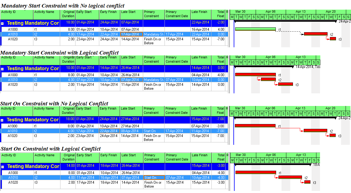
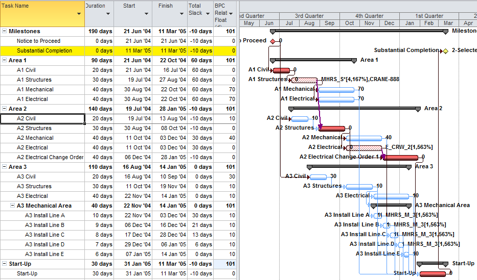
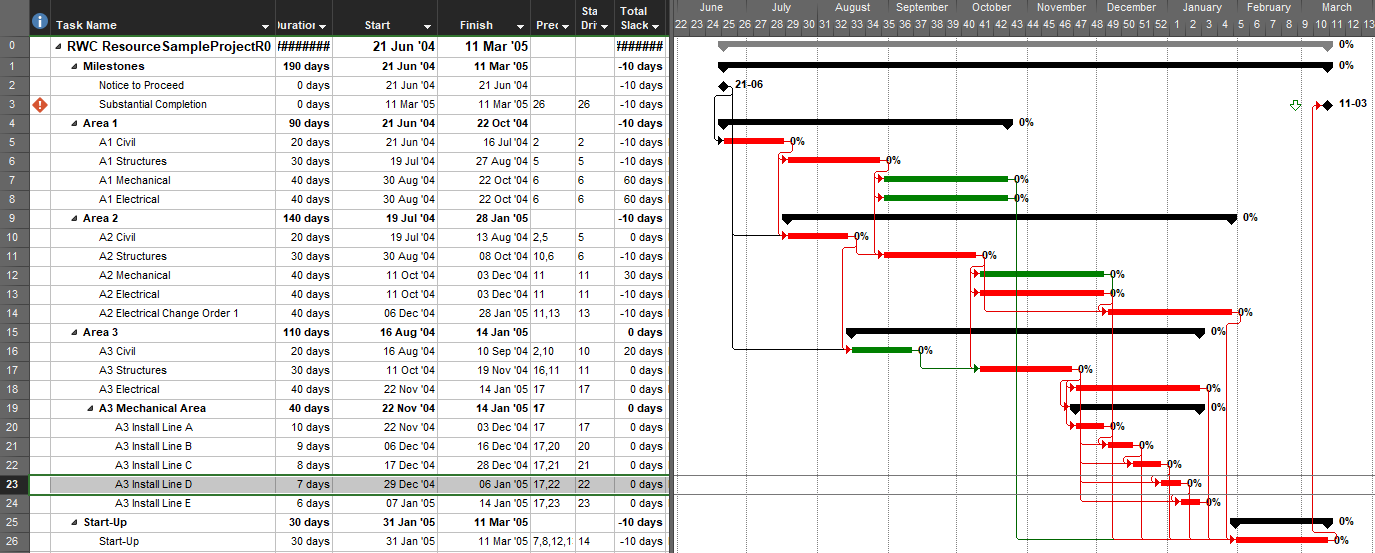
Consider the example of the small installation project presented below. There is a deadline on the “Substantial Completion” milestone, and the project is 10-days behind schedule. For unrelated reasons, the project manager has identified a need to examine the predecessor and successor logic paths around one task – “A3 Install Line D” – which is selected in the figure.


Task Inspector

We can first examine the task’s dependencies using MSP’s Task Detail Form and the Task Inspector pane.  The form shows that the task has two finish-to-start predecessors and two finish-to-start successors, but it provides no other schedule information for these dependencies.  Task Inspector identifies the second predecessor — ID 22 – A3 Install Line C — as the driving predecessor.  That is the predecessor whose logic is controlling the start date for our task.

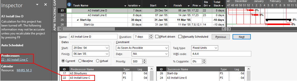
This driving predecessor is hyperlinked, so clicking on it automatically selects the corresponding task in the task table and updates the details.  In addition, a new “Go back to” task link is added to the Inspector pane.  Starting from a specific ending task, the user can use these tools to “click-trace” backwards and forwards along the driving predecessor logic path to the selected task.

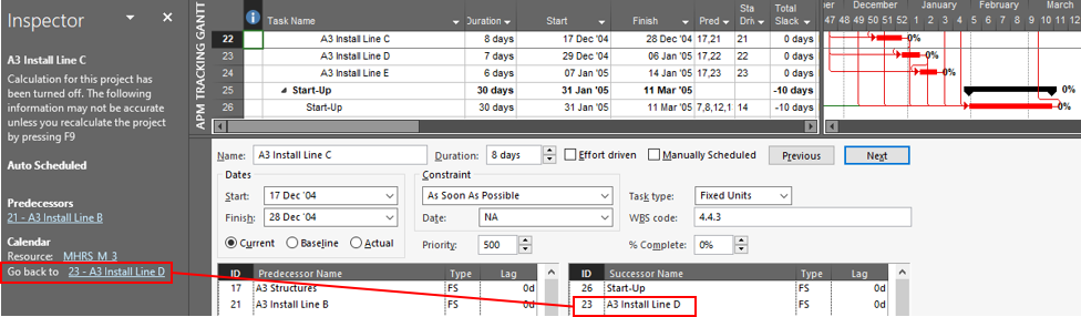
Click-tracing of driven successor paths is not possible using the Inspector pane, and predecessors that are hidden by filtering or outlining can’t be traced.  Moreover, neither external links nor resource-driving links can be traced.  Finally, the driving predecessors can be incorrect when relationships other than finish-to-start are used.

BPC Logic Filter – Task Logic Inspector

The Logic Inspector in BPC Logic Filter presents consolidated views of a task’s driving and non-driving predecessors and successors, including other relevant information like dates, resources, or user-selected fields.  Driving relationships are highlighted and listed at the top, while links to inactive predecessors are de-emphasized and listed at the bottom.  For logical significance, the ERF column indicates how far (in days) the predecessor is from controlling/driving the successor’s early dates, and the LRF column indicates how far the successor is from controlling/driving the predecessor’s late dates.  The latter is most useful when click-tracing to explore successor logic paths.  (The yellow-on-red color scheme in the figure highlights relationships that are driving in both directions.)

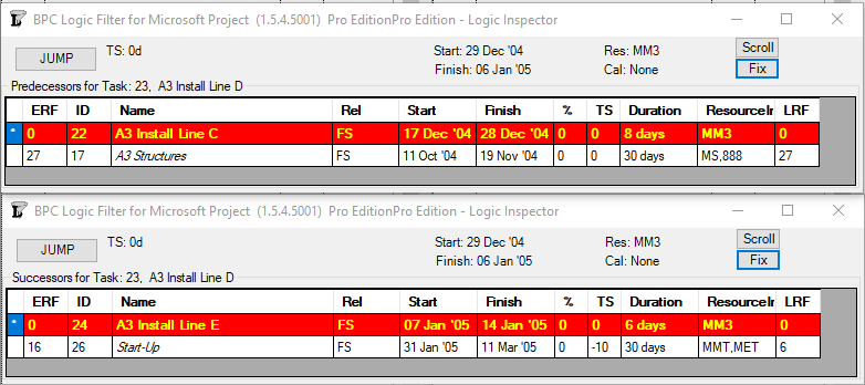
With the Jump buttons in the Logic Inspector windows, users can click-trace logic paths forward and backward through the project schedule.  Unlike the built-in tools, the Logic Inspector windows allow inspection and click-tracing of both driving and non-driving logic along successor paths, external (i.e. master/sub-project) paths, resource-constrained logic paths, and hierarchical logic paths.

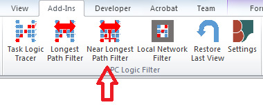
Task Paths and Task Path Filters

Recent versions of MS Project (2013+) include Task Path bar styles for graphically highlighting predecessor and successor paths on the Gantt chart.  In addition, it is possible to use a simple “QuickTrace” macro (like the one linked above or one of the freeware settings in BPC Logic Filter), to identify the same set of related tasks.  In the next figure, the Path Predecessors bar style has been applied to color the bars of all tasks that are path predecessors of the selected one.  The QuickTrace macro (included in BPC Logic Filter) has also been used to highlight the same related tasks.

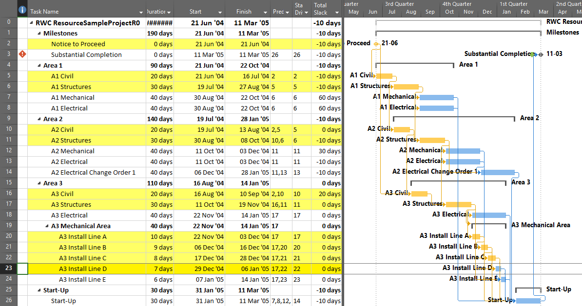
Alternately, QuickTrace can display the related tasks using a filter rather than a highlighter, as shown below.  In either case, the actual driving logic for the selected task is not apparent.  (And no, Total Slack does not define driving logic for this task.)

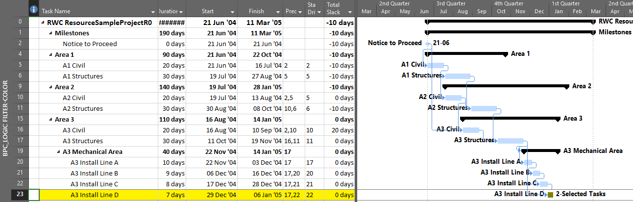
The next figure displays both the Path Predecessors (orange) and the Path Driving Predecessors (red-orange) bar styles for the selected task, and QuickTrace has been used to highlight the driving predecessors in the table.  A corresponding filter could also be applied.

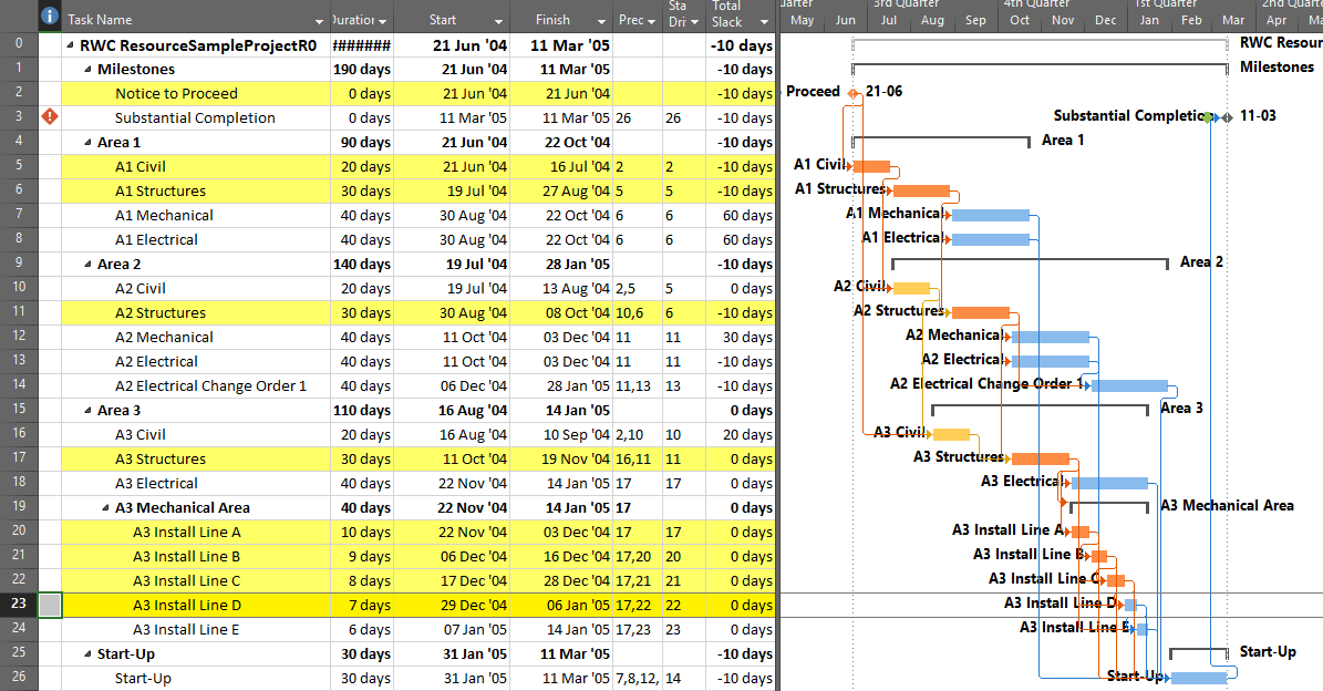
Although generally less useful for analysis, corresponding bar styles and filters can be applied for the path successors and path driven successors of the selected task.

BPC Logic Filter – Advanced Tracing

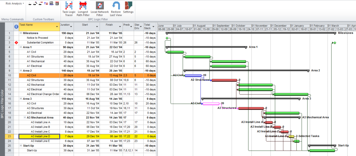
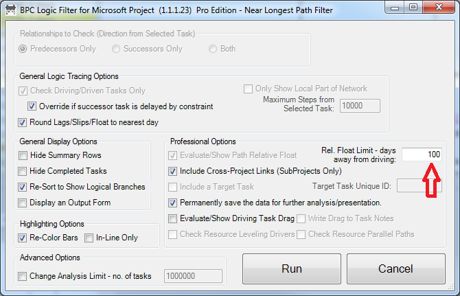
With advanced logic analysis features, the relative float of all the predecessor task paths can be defined and displayed.  The following chart shows the entire project, with the predecessor paths of the selected task highlighted according to their path relative float in days.  (Path relative float indicates how much a particular task or path may be delayed before affecting the selected task; i.e. “days away from driving”.)  Path relative float is indicated numerically at the right side of each related bar.  Unrelated bars are de-emphasized and colored green.  The bar chart shown is similar to that obtained using the Task Path bar styles, with the key exception that non-driving predecessor paths can be ranked.

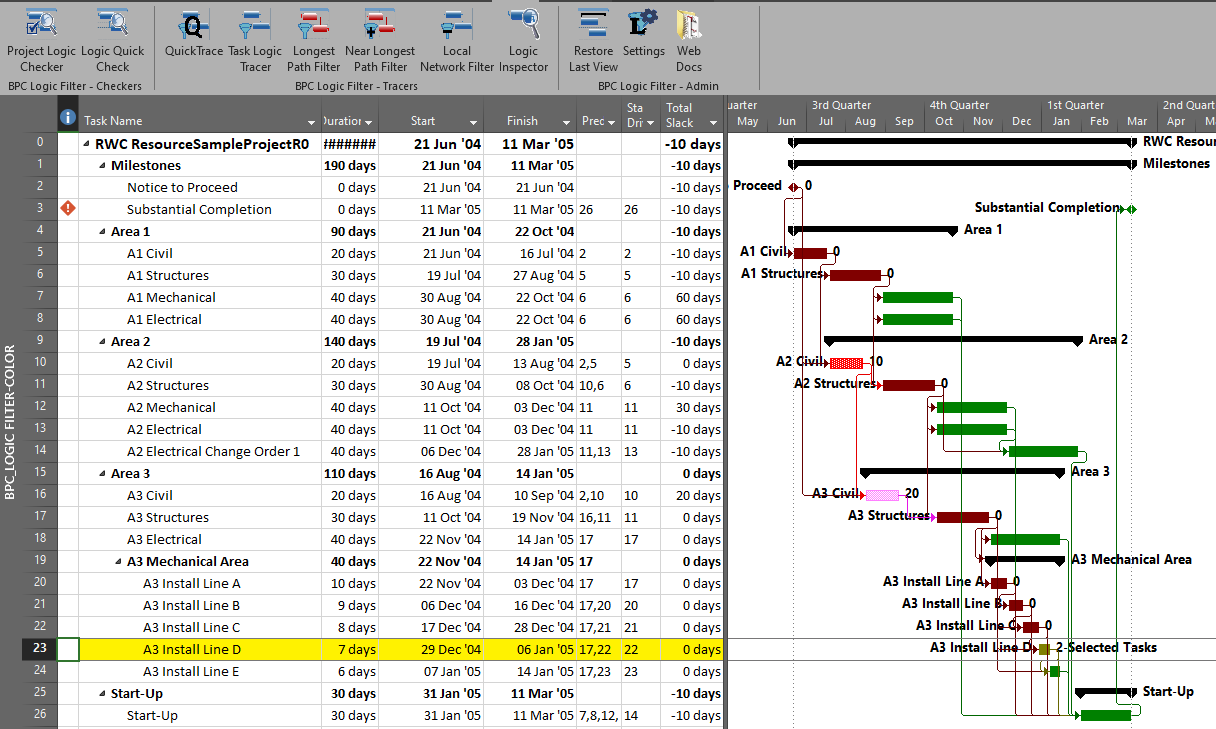
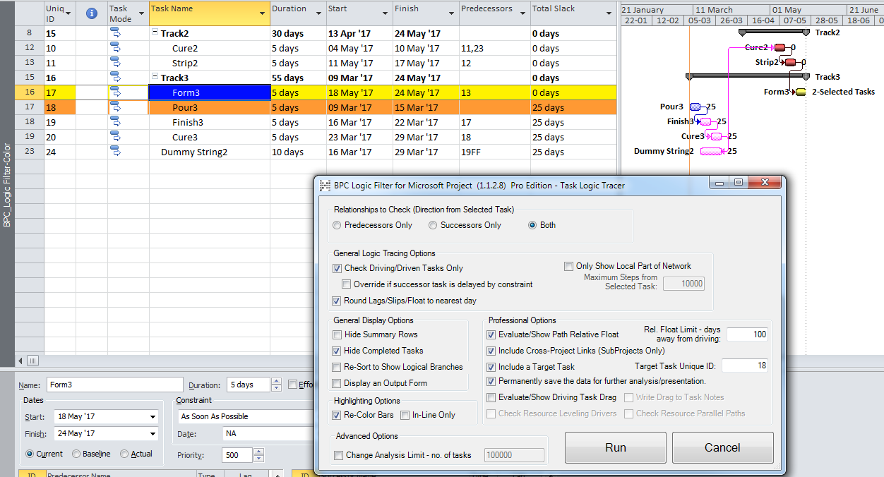
BPC Logic Filter allows one variation – bounded network analysis – to only show connections to a particular target task.  The figure below highlights the connections between the selected task, A3 Install Line D, and the target task, A2 Civil.

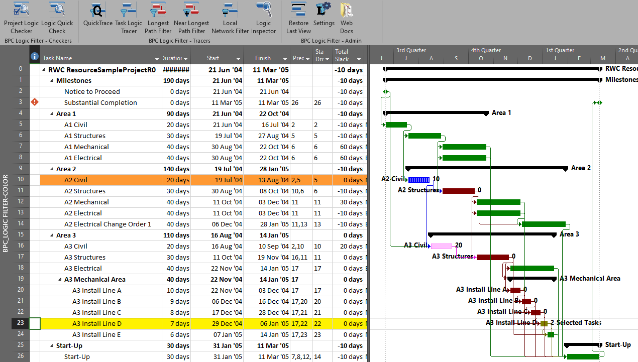
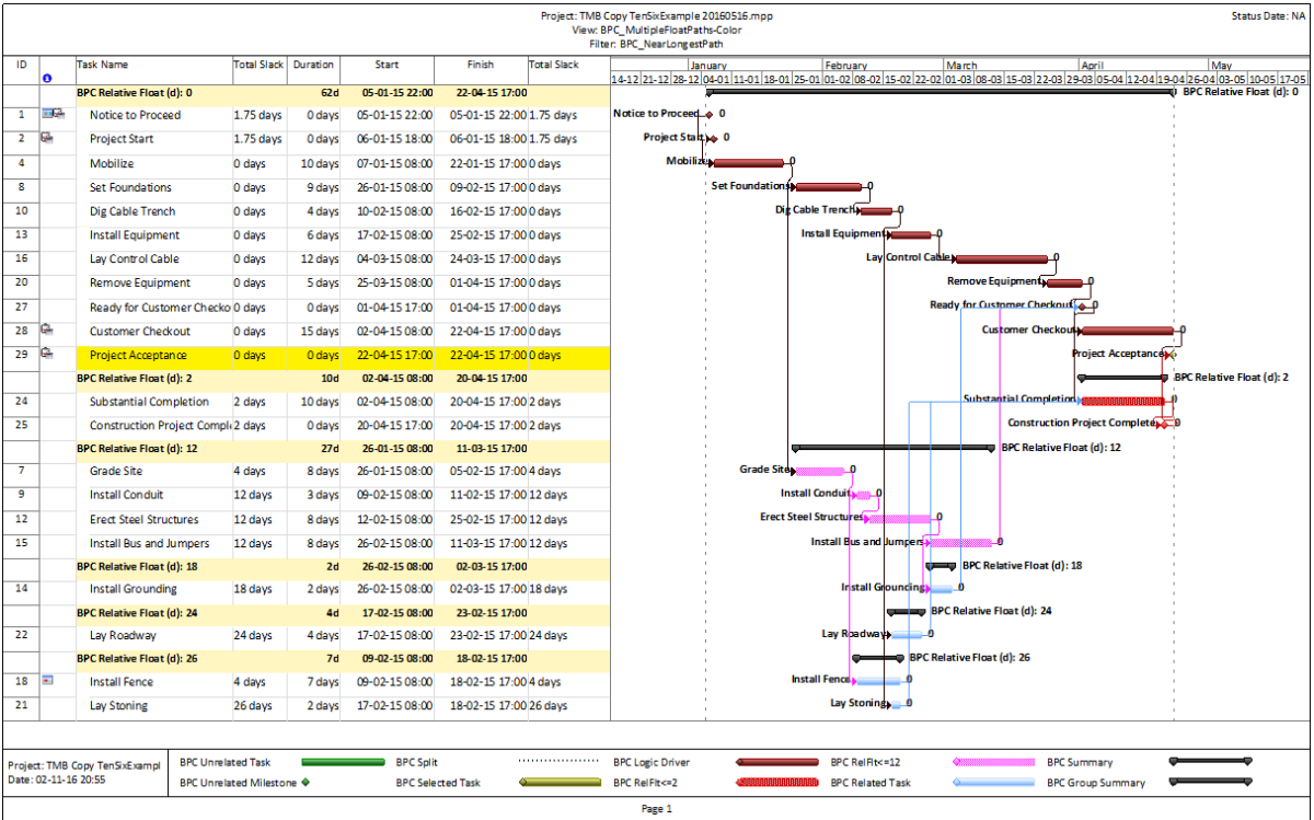
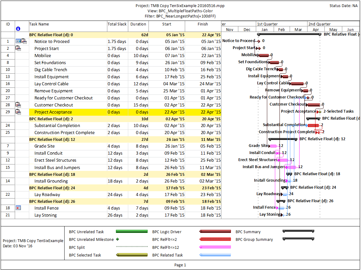
The previous two figures displayed the related task paths in-line and within the context of the overall project view.  A more focused view of the driving and near-driving paths is provided by applying a filter to hide all unrelated tasks, as shown here.

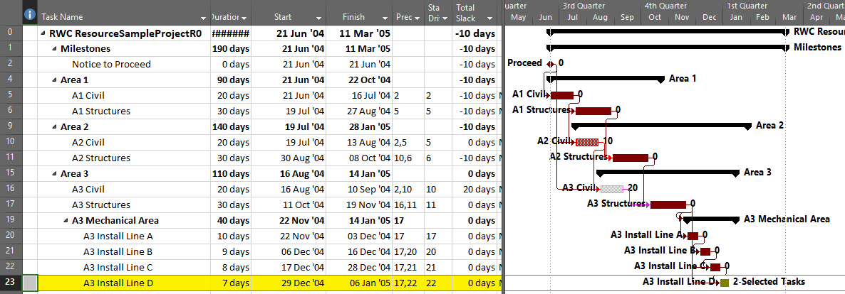
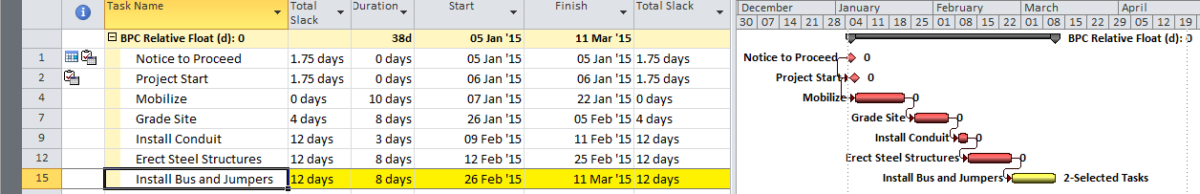
It is often useful to group and sort tasks to clearly display the chain of driving logic and associated near-driving paths.  The first group in the figure below – “BPC Relative Float (d): 0” – indicates the driving logical path for the selected activity.  The next two groups depict branching logical paths (one task each) that are 10- and 20-days away from driving the selected task.

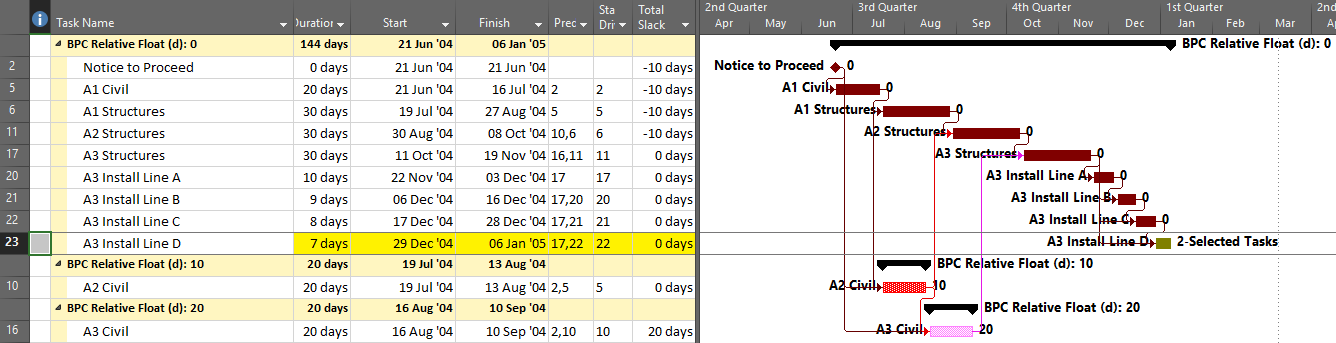
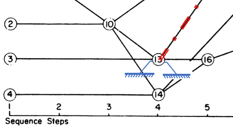
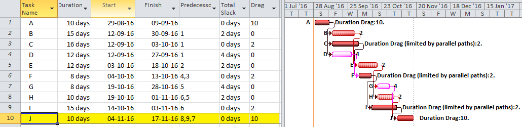
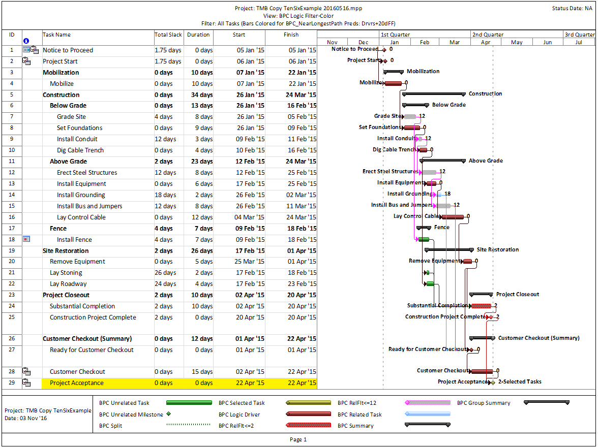
Finally, when attempting to accelerate a task by shortening its driving logical path, Drag quantifies the maximum acceleration that may be gained by shortening a particular task along that path.  Drag is limited by the existence of parallel paths, as clearly evidenced by Tasks 6 and 11 in the figure below.  For focused acceleration of complex projects, the Drag metric can assist in prioritizing actions.

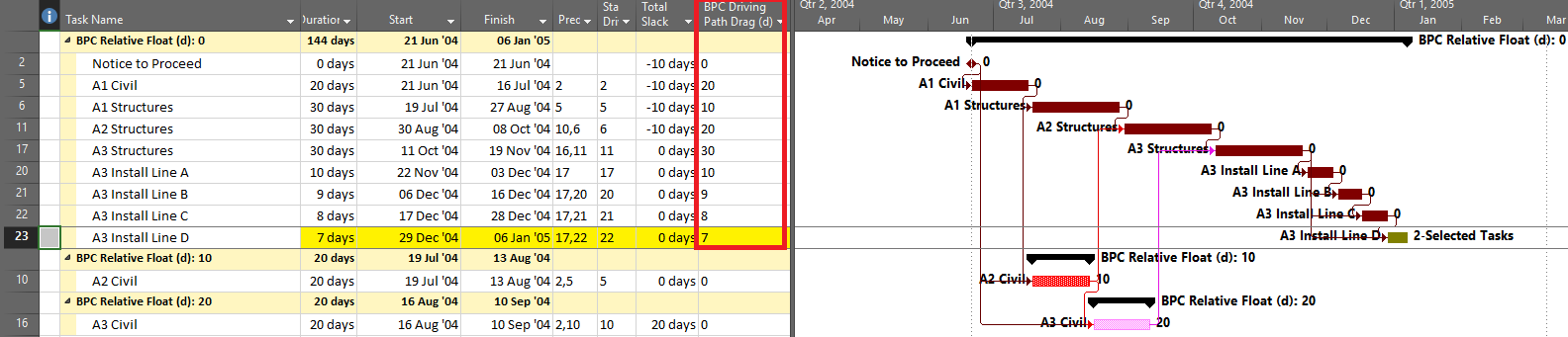
The examples shown here represent successively more powerful analyses of driving logic for an arbitrary task in a project schedule.  If that task were the final task or a key completion milestone for the project, then the resulting special case of the driving path would be the “Critical Path” for the project.

See a related video entry:

Video – Logic Tracing Example in Microsoft Project